BISDK02BI-03 Laird Technologies, BISDK02BI-03 Datasheet - Page 3
BISDK02BI-03
Manufacturer Part Number
BISDK02BI-03
Description
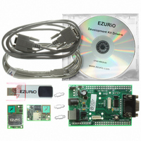
KIT BISM II BLUETOOTH/802.11B/G
Manufacturer
Laird Technologies
Series
EZURiOr
Type
Bluetooth 2.0, Wireless LANr
Specifications of BISDK02BI-03
Frequency
2.4GHz
Interface Type
RS-232, USB
Technology/ Type
Development Kit
For Use With/related Products
EZURiO embedded Bluetooth and Wireless LAN modules
Lead Free Status / RoHS Status
Lead free / RoHS Compliant
Lead Free Status / RoHS Status
Lead free / RoHS Compliant, Lead free / RoHS Compliant


Jumper JP2 is used to select an external power source on the screw terminals.
SW1 (slide switch) provides the power on / off for the module but does not isolate the
power from other components of the development board.
S1 (push button TACT switch) provides a reset signal to both the 40 way and 50 way
connectors. Note that the reset polarity is different for the 40 and 50 way pinouts. This
is accomplished by circuitry on the development board, providing an active HIGH reset
for the 40 way connector and an active LOW for the 50 way connector. Users connecting
a reset signal to the test points one the board, should be aware that there is a 10kΩ
pulldown on the 40 way reset pin, and a open collector transistor connected to the 50
way reset pin. Refer to the schematics on the CD.
An alternative method of powering the development kit is to supply power to Pin 9 of the RS232
connector.
If this method is used, no other power supplies should be connected to the board.
Jumper 8 on the development board needs to be moved to allow power to be derived from pin 9 of
the serial port. In this mode the ring indicator will not be available from the RS232 interface.
5.
RS-232 Serial Interface
This provides a direct interface to any standard RS-232 port on a PC or peripheral. The 9
way D type connector can be plugged straight into a serial port on a PC or peripheral. If
access to the serial port is restricted, the serial cable provided can be used to connect
the development board to the PC.
The development board contains a level shifter on the RX, TX, CTS, RTS, DTR, DSR, RI
and DCD signals that converts between the 3.3V levels required on the module to the
standard RS-232 levels.
APN_06008_1v0 Wireless Development Kit Manual.doc
Page 3
Related parts for BISDK02BI-03
Image
Part Number
Description
Manufacturer
Datasheet
Request
R

Part Number:
Description:
Bluetooth Serial Module Development Kit
Manufacturer:
Laird Technologies
Part Number:
Description:
BLUETOOTH MODULE DEVELOPMENT KIT
Manufacturer:
Laird Technologies
Part Number:
Description:
Bluetooth 2.0 AT Data Module, Internal Antenna Development Kit
Manufacturer:
Laird Technologies

Part Number:
Description:
BLUETOOTH EVAL BOARD BTM511
Manufacturer:
Laird Technologies
Datasheet:

Part Number:
Description:
Bluetooth / 802.15.1 Modules & Development Tools BLUETTH Multimed MODLE, No ANT DEVKIT
Manufacturer:
Laird Technologies
Datasheet:

Part Number:
Description:
DEV KIT PRM122
Manufacturer:
Laird Technologies
Datasheet:
Part Number:
Description:
DEV KIT PRM123
Manufacturer:
Laird Technologies
Datasheet:

Part Number:
Description:
KIT FOR PRM112
Manufacturer:
Laird Technologies
Datasheet:
Part Number:
Description:
DEV KIT PRM121
Manufacturer:
Laird Technologies
Datasheet:

Part Number:
Description:
KIT DEVELOPMENT FOR LT2510 U.FL
Manufacturer:
Laird Technologies
Datasheet:

Part Number:
Description:
CHOKE COMMON MODE 110 OHMS SMD
Manufacturer:
Laird Technologies
Datasheet: