DNT2400DK RFM, DNT2400DK Datasheet - Page 5
DNT2400DK
Manufacturer Part Number
DNT2400DK
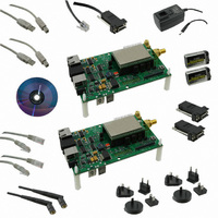
Description
DEVELOPMENT KIT FOR DNT2400 MOD
Manufacturer
RFM
Type
Transceiverr
Specifications of DNT2400DK
Frequency
2.4GHz
Product
RF Development Tools
Maximum Frequency
2.4 GHz
Supply Voltage (max)
3.3 V
Supply Voltage (min)
0 V
For Use With/related Products
DNT2400
Lead Free Status / RoHS Status
Lead free / RoHS Compliant
Other names
583-1150
Available stocks
Company
Part Number
Manufacturer
Quantity
Price
Company:

Part Number:
DNT2400DK
Manufacturer:
RFM
Quantity:
12 800


DNT2400C RFIO Stripline
The DNT2400C has a U.FL coaxial connector mounted near pad 42 for antenna connection (see Antenna Con-
nector discussion below). It is also possible to connect an antenna using a stripline from pad 42. It is important
www.RFM.com E-mail: info@rfm.com
©2009 by RF Monolithics, Inc.
Pin
30
31
32
33
34
35
36
37
38
39
40
41
42
43
/HOST_CTS
RADIO_TXD
RADIO_RXD
/HOST_RTS
/RESET
VMOD
Name
RSVD
RSVD
RSVD
RSVD
RSVD
RFIO
GND
GND
I/O
I/O
O
O
O
-
-
-
-
-
-
-
I
I
I
UART flow control input. The host sets this line low to allow data to flow from the DNT2400 on the
RADIO_TXD pin. When the host sets this line high, the DNT2400 will stop sending data to the host.
UART transmitter output. The DNT2400 sends serial data to the host on this pin.
UART receiver input. The DNT2400 receives serial data from the host on this pin.
UART flow control output. The DNT2400 sets this line low to indicate it is ready to accept data from the host
on the RADIO_RXD input. When the DNT2400 sets this line high, the host must stop sending data.
Module’s +3.3 V regulated supply. Connect to pad 3 to support 3.3 V full scale and/or ratiometric ADC read-
ings, etc. Current drain on this output should be no greater than 5 mA.
Reserved pin. Leave unconnected.
Reserved pin. Leave unconnected.
Reserved pin. Leave unconnected.
Reserved pin. Leave unconnected.
Active low module hardware reset.
Reserved pin. Leave unconnected.
RF ground for the DNT2400C only. Connect to the host circuit board ground plane.
Alternate RF port for the DNT2400C only. The antenna can be connected to this port with a 50 ohm stripline
or coaxial cable. Leave unconnected when using the U.FL connector.
RF ground for the DNT2400C only. Connect to the host circuit board ground plane.
Figure 2
Description
DNT2400 - 08/12/09
Page 5 of 7
Related parts for DNT2400DK
Image
Part Number
Description
Manufacturer
Datasheet
Request
R

Part Number:
Description:
ASH RX 115.2 KBPS 433.92 MHZ
Manufacturer:
RFM
Datasheet:

Part Number:
Description:
RFIC TRANCEIVER MULTI-CHANNEL FS
Manufacturer:
RFM
Datasheet:

Part Number:
Description:
ASH TX 115.2 KBPS 433.92 MHZ
Manufacturer:
RFM
Datasheet:
Part Number:
Description:
Filters 1602MHz BW=61MHz
Manufacturer:
RFM
Datasheet:

Part Number:
Description:
RESONATOR, SM3030-6
Manufacturer:
RFM
Datasheet:

Part Number:
Description:
RESONATOR, SM3030-6
Manufacturer:
RFM
Datasheet:

Part Number:
Description:
RESONATOR, SM3030-6
Manufacturer:
RFM
Datasheet:

Part Number:
Description:
RESONATOR, SM5035-4
Manufacturer:
RFM
Datasheet:
Part Number:
Description:
RESONATOR 418MHZ SM5035-4
Manufacturer:
RFM
Datasheet:
Part Number:
Description:
RESONATOR 315 MHZ SMD
Manufacturer:
RFM
Datasheet:

Part Number:
Description:
10-Terminal Ceramic Surface-Mount Case 7 x 5 mm Nominal Footprint
Manufacturer:
RFM [RF Monolithics, Inc]
Datasheet:
Part Number:
Description:
QUAD-BAND GSM850/GSM/DCS/PCS POWER AMP MODULE
Manufacturer:
RFM [RF Monolithics, Inc]
Datasheet:
Part Number:
Description:
402 to 405 MHz Medical Band Front-end Filter
Manufacturer:
RFM [RF Monolithics, Inc]
Datasheet:
Part Number:
Description:
674.03 MHz SAW Resonator
Manufacturer:
RFM [RF Monolithics, Inc]
Datasheet: