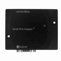
CB-SPA312I-02 ConnectBlue, CB-SPA312I-02 Datasheet - Page 13

CB-SPA312I-02
Manufacturer Part Number
CB-SPA312I-02
Description
SERIAL PORT ADAPTER 312I BTOOTH
Manufacturer
ConnectBlue
Series
CB-SPAr
Datasheet
1.CB-SPA312I-02.pdf
(29 pages)
Specifications of CB-SPA312I-02
Function
Transceiver, Bluetooth
Modulation Or Protocol
Bluetooth v2.0, Class 1
Frequency
2.4GHz
Applications
General Purpose
Interface
RS-232
Data Rate - Maximum
54Mbps
Features
Wireless Multidrop™
Voltage - Supply
4 V ~ 6 V
Package / Case
Packaged Unit
Lead Free Status / RoHS Status
Lead free / RoHS Compliant
Power - Output
-
Sensitivity
-
Other names
809-1026
•
•
•
•
•
•
The model is designed to operate as a DTE (Data Terminal Equipment). When connecting
the Serial Port Adapter to a DCE (Data Communication Equipment), e.g. a modem, a regular
modem cable, straight cable, shall be used. When connecting the Serial Port Adapter to
another DTE, e.g. a PC, a crossover serial cable must be used. The crossover cable must have
TD and RD crossed (pins 2-3 and 3-2), RTS and CTS crossed (pins 7-8 and 8-7) and
optionally DTR and DSR crossed (pins 4-6 and 6-4).
2.2.4 Buttons and LED
If the
well as the default escape sequence are restored. If the
pressed and a remote peer is configured for “external connect” the connect attempt is
initiated. See AT Command Specification for further details.
The status LED uses the following color indications.
Pin 4: DTR, output, data terminal ready
Pin 5: GND, ground
Pin 6: DSR, input, data set ready
Pin 7: RTS, output, request to send
Pin 8: CTS, input, clear to send
Pin 9: NC, not connected
restore button
(see Picture 5) is pressed during power on, the default serial settings as
DTR, 4
GND, 5
DSR, 6
GND, 5
DSR, 6
RTS, 7
CTS, 8
DTR, 4
RTS, 7
CTS, 8
RD, 2
TD, 3
RD, 2
TD, 3
Picture 6. Crossover cable
Picture 7. Straight cable
function button
GND, 5
GND, 5
DTR, 4
DSR, 6
DSR, 4
DTR, 6
RTS, 7
CTS, 8
CTS, 7
RTS, 8
RD, 3
RD, 2
TD, 3
TD, 2
(see Picture 5) is
13


