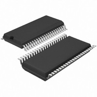
T4260-ILSH Atmel, T4260-ILSH Datasheet - Page 16

T4260-ILSH
Manufacturer Part Number
T4260-ILSH
Description
IC AM/FM FRONT END W/PLL 44SSOP
Manufacturer
Atmel
Datasheet
1.T4260-ILQH.pdf
(34 pages)
Specifications of T4260-ILSH
Frequency
AM, FM
Modulation Or Protocol
AM, FM
Applications
AM/FM Radio Receiver
Current - Receiving
85mA
Data Interface
PCB, Surface Mount
Antenna Connector
PCB, Surface Mount
Voltage - Supply
8 V ~ 10 V
Operating Temperature
-40°C ~ 85°C
Package / Case
44-SSOP
Lead Free Status / RoHS Status
Lead free / RoHS Compliant
Features
-
Sensitivity
-
Memory Size
-
Data Rate - Maximum
-
10.6
10.7
16
Reception Mode
RF-AGC
T4260
The AM and FM RF-AGC controls the current into the AM and FM pin diodes (FM pin 3 and AM
pin 9) to limit the level at the AM or FM mixer input. If the level at the AM or FM mixer input
exceeds the selected threshold, then the current into the AM or FM pin diodes increases. If this
step is not sufficient in AM mode, the source drain voltage of the MOSFET (pin 11) can be
decreased. In AM mode, the time constants can be selected by the external capacitors at pin 42
(RFAGCA1) and at pin 12 (RFAGCAM2) and in FM mode by an external capacitor at pin 33
(RFAGCFM). In AM mode, the double pole (by the capacitors at pin 42 and pin 12) allows a bet-
ter harmonic distortion by a higher time constant.
The RF-AGC can be controlled in 1-dB steps by setting the bits 12 to 15. The values for FM and
AM are controlled by bit 17.
Table 10-8.
There are two different operation modes, AM and FM, which are selected by means of bit 17 and
bit 145 according to
the AM mixer, the AM RF-AGC, the AM divider (prescaler) and the IF AM amplifier (input at
pin 35) are activated. In FM mode (bit 17 = 0), the FM mixer, the FM RF-AGC and the IF FM
amplifier (input at pin 36) are activated.
In AM or FM reception mode, bit 145 has to be set to the corresponding mode. The buffer ampli-
fier input can be connected to pin 16 (with the external FM loop filter) by bit 145 = 0 and to pin 17
(with the external AM loopfilter) by bit 145 = 1.
The AM/FM function for the tuner part is controlled by bit 17 as given in
Table 10-9.
RF-AGC AM
102 dBµV
103 dBµV
88 dBµV
89 dBµV
90 dBµV
91 dBµV
92 dBµV
...
RF-AGC
Tuner Operating Modes
Table 9-1 on page 12
AM/FM
FM
AM
RF-AGC FM
105 dBµV
106 dBµV
91 dBµV
92 dBµV
93 dBµV
94 dBµV
95 dBµV
...
and
B15
Table 10-1 on page
...
0
0
0
0
0
1
1
B14
...
0
0
0
0
1
1
1
14. In AM mode (bit 17 = 1),
B17
0
1
Table
B13
...
0
0
1
1
0
1
1
10-9.
4528N–AUDR–11/09
B12
...
0
1
0
1
0
0
1


