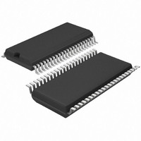
T4260-ILSH Atmel, T4260-ILSH Datasheet - Page 27

T4260-ILSH
Manufacturer Part Number
T4260-ILSH
Description
IC AM/FM FRONT END W/PLL 44SSOP
Manufacturer
Atmel
Datasheet
1.T4260-ILQH.pdf
(34 pages)
Specifications of T4260-ILSH
Frequency
AM, FM
Modulation Or Protocol
AM, FM
Applications
AM/FM Radio Receiver
Current - Receiving
85mA
Data Interface
PCB, Surface Mount
Antenna Connector
PCB, Surface Mount
Voltage - Supply
8 V ~ 10 V
Operating Temperature
-40°C ~ 85°C
Package / Case
44-SSOP
Lead Free Status / RoHS Status
Lead free / RoHS Compliant
Features
-
Sensitivity
-
Memory Size
-
Data Rate - Maximum
-
11.3
11.4
4528N–AUDR–11/09
PLL Core Block Diagram Description
High-speed Tuning
The two N-dividers are stored in two 18-bit memory register (LATCH N-DIV) and the R-divider in
a 14-bit memory register (LATCH R-DIV). One of the two N-dividers (N1 or N2) can be activated
by bit 5 as active N-divider (with the 18-bit multiplexer MUX).
The (divider) 2-bit shift mode can be activated with bit 32 = 0. The N- and R-divider are shifted
two bits to the right in this shift mode. Because the two lowest R-divider bits (bit 124 and bit 125)
are 0 they do not have to be evaluated. In opposite to the R-divider the lowest two N-divider bits
(bit 102 and bit 103 or bit 80 and bit 81, depends on the active N-divider) are special evaluated
in the ACCU block if fractional mode is active (bit 144 = 0). The two lowest N- and R-divider bits
are also called shift bits.
The SWITCH N+1, N block is steering the division through N or N+1 in the N-divider if fractional
and 2-bit shift mode are active. There is only a division by N if the fractional mode is deactivated
in 2-bit shift mode.
The output signals of the 18-bit N-divider and 14-bit R-divider will be compared in the
PHASEDETECTOR which one activates the sink and source currents of the charge pumps
(CP).
There are also two HCDEL registers (for the high current CP delay time) but only one of them is
active. One of the HCDEL registers can be activated by bit 18. The delay time of the HCDEL
register can be selected with bit 20 and bit 21 or bit 22 and bit 23). The current for the high CP
(HCCP) can be set by bit 62 and the current for the low current CP (LCCP) by bit 63.
With bit 145 the AM- or FM-Loopfilter (pin) can be activated. It is also possible to use the
AM-Loopfilter in FM mode (instead of the FM-Loopfilter) or the FM-Loopfilter in AM mode.
The fractional mode (bit 144 = 0) in connection with the direct shift mode (bit 32 = 0) allows very
fast frequency changes with four times the step frequency (50 kHz = 4
steps (e.g., f
the right (this corresponds to a R- and N-divider division by 4 or a step frequency multiplication
by 4).
Due to the 2-bit shift, a faster tuning response time of approximately 1 ms instead of 3-4 ms for a
tune over the whole FM band from 87.5 MHz to 108 MHz is possible with f
If the FM receiving frequency is 103.2125 MHz (with e.g. f
N-divider of 9113 and an R-divider of 12 are necessary when using a reference-frequency (f
of 150 kHz.
An important condition for the use of the fractional mode is an R-divider with an integer value
after the division by 4 (R-dividers have to be a multiple of 4).
After a 2-bit shift (divider division by 4), the R-divider is now 3 (instead of 12) and the N-divider is
2278.25 (instead of 9113). The new N-divider of 2278.25 is also called ¼ fractional step
because the modulo value of the N-divider is 0.25 = ¼. In total, there are 4 different fractional
2-bit shift steps: full, ¼, ½ and ¾ step.
PDF
f
f
VCO
PDF
= 12.5 kHz). In direct shift mode, the R- and the N-divider are shifted by 2 bits to
= f
= f
VCO
IF
+ f
/N = f
rec
= 10.7 MHz + 103.2125 MHz = 113.9125 MHz
ref
/R = 113.9125 MHz/9113 = 150 kHz/12 = 12.5 kHz
PDF
= 12.5 kHz and f
f
PDF
PDF
) at low frequency
IF
= 12.5 kHz.
= 10.7 MHz), an
T4260
ref
27
)


