APT75GN120JDQ3 Microsemi Power Products Group, APT75GN120JDQ3 Datasheet

IGBT 1200V 124A 379W SOT227

APT75GN120JDQ3

Manufacturer Part Number
APT75GN120JDQ3
Description
IGBT 1200V 124A 379W SOT227
Manufacturer
Microsemi Power Products Group
Datasheet

Specifications of APT75GN120JDQ3

Igbt Type
Field Stop and Trench
Configuration
Single
Voltage - Collector Emitter Breakdown (max)
1200V
Vce(on) (max) @ Vge, Ic
2.1V @ 15V, 75A
Current - Collector (ic) (max)
124A
Current - Collector Cutoff (max)
200µA
Input Capacitance (cies) @ Vce
4.8nF @ 25V
Power - Max
379W
Input
Standard
Ntc Thermistor
No
Mounting Type
Chassis Mount
Package / Case
ISOTOP
Lead Free Status / RoHS Status
Lead free / RoHS Compliant
Other names
APT75GN120JDQ3MI
APT75GN120JDQ3MI
TYPICAL PERFORMANCE CURVES
Utilizing the latest Field Stop and Trench Gate technologies, these IGBT's have ultra
low V
conduction loss. Easy paralleling is a result of very tight parameter distribution and
a slightly positive V
extremely reliable operation, even in the event of a short circuit fault. Low gate charge
simplifies gate drive design and minimizes losses.
• Trench Gate: Low V
• Easy Paralleling
• Intergrated Gate Resistor: Low EMI, High Reliability
Applications: Welding, Inductive Heating, Solar Inverters, SMPS, Motor drives, UPS
MAXIMUM RATINGS
STATIC ELECTRICAL CHARACTERISTICS
V
Symbol
Symbol
T
V
V
1200V Field Stop
SSOA
R
(BR)CES
V
J
CE(ON)
GE(TH)
I
I
V
I
,T
I
I
GES
P
CES
G(int)
T
CES
CM
C1
C2
GE
CE(ON)
D
L
STG
CAUTION: These Devices are Sensitive to Electrostatic Discharge. Proper Handling Procedures Should Be Followed.
and are ideal for low frequency applications that require absolute minimum
Parameter
Collector-Emitter Voltage
Gate-Emitter Voltage
Continuous Collector Current @ T
Pulsed Collector Current
Switching Safe Operating Area @ T
Total Power Dissipation
Operating and Storage Junction Temperature Range
Max. Lead Temp. for Soldering: 0.063" from Case for 10 Sec.
Characteristic / Test Conditions
Collector-Emitter Breakdown Voltage (V
Gate Threshold Voltage
Collector-Emitter On Voltage (V
Collector Cut-off Current (V
Gate-Emitter Leakage Current (V
Intergrated Gate Resistor
CE(ON)
CE(on)
temperature coefficient. A built-in gate resistor ensures
1
(V
CE
CE
CE
= V
= 1200V, V
= 1200V, V
APT Website - http://www.advancedpower.com
®
GE
GE
C
C
GE
GE
J
= 25°C
= 110°C
= 15V, I
= 15V, I
= 150°C
= ±20V)
, I
C
GE
= 3mA, T
GE
GE
C
C
= 0V, I
= 75A, T
= 75A, T
= 0V, T
= 0V, T
j
C
= 25°C)
= 3mA)
j
j
= 25°C)
= 125°C)
j
j
= 25°C)
= 125°C)
All Ratings: T
2
2
C
= 25°C unless otherwise specified.
1200
MIN
5.0
1.4
APT75GN120JDQ3
225A @ 1200V
-55 to 150
APT75GN120JDQ3
1200
TYP
±30
124
225
379
300
5.8
1.7
2.0
57
10
APT75GN120JDQ3
ISOTOP
G
1200V
MAX
TBD
200
600
6.5
2.1
®
"UL Recognized"
file # E145592
C
E
Amps
Watts
UNIT
Units
Volts
Volts
°C
µA
nA

Related parts for APT75GN120JDQ3

APT75GN120JDQ3 Summary of contents

Page 1

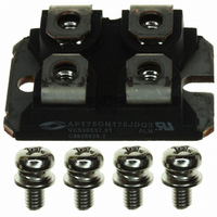
... 1200V 0V 125° ±20V) GE APT Website - http://www.advancedpower.com 1200V APT75GN120JDQ3 APT75GN120JDQ3 ISOTOP ® 25°C unless otherwise specified. C APT75GN120JDQ3 1200 ±30 124 57 225 225A @ 1200V 379 -55 to 150 300 MIN TYP MAX 1200 5.0 5.8 6.5 1.4 1.7 2.1 2.0 ...

Page 2

Characteristic Symbol C Input Capacitance ies C Output Capacitance oes C Reverse Transfer Capacitance res V Gate-to-Emitter Plateau Voltage GEP Q 3 Total Gate Charge g Q Gate-Emitter Charge ge Q Gate-Collector ("Miller ") Charge gc SSOA Switching Safe Operating ...

Page 3

V = 15V GE 140 T = -55°C J 120 T = 25°C J 100 T = 125° 0.5 1.0 1.5 2.0 2.5 3 COLLECTER-TO-EMITTER VOLTAGE (V) CE FIGURE 1, ...

Page 4

V = 15V 800V 25°C or =125° 1.0Ω 100µ COLLECTOR TO EMITTER CURRENT (A) CE FIGURE 9, ...

Page 5

... T = 125 C J ° 6. 800V 1.0Ω 100 110 120 I , COLLECTOR CURRENT (A) C Figure 20, Operating Frequency vs Collector Current APT75GN120JDQ3 200 400 600 800 1000 1200 1400 , COLLECTOR TO EMITTER VOLTAGE CE Note Duty Factor Peak θ 1 min (f max f = max1 t d(on ...

Page 6

APT60DQ120 D.U.T. Figure 21, Inductive Switching Test Circuit 90% Gate Voltage t d(off) Collector Voltage 90 10% Collector Current 0 Switching Energy Figure 23, Turn-off Switching Waveforms and Definitions 10% t ...

Page 7

... RECTANGULAR PULSE DURATION (seconds) RC MODEL Junction temp. (°C) 0.148 Power 0.238 (watts) 0.174 Case temperature. (°C) FIGURE 25b, TRANSIENT THERMAL IMPEDANCE MODEL APT75GN120JDQ3 = 25°C unless otherwise specified. C APT75GN120JDQ3 60 73 540 MIN TYP MAX 2.8 3.48 2.17 MIN TYP MAX 25°C ...

Page 8

T = 175°C J 120 100 T = 125° -55° ANODE-TO-CATHODE VOLTAGE (V) F Figure 26. Forward Current vs. ...

Page 9

... Package Outline W=4.1 (.161) W=4.3 (.169) H=4.8 (.187) H=4.9 (.193) (4 places) 4.0 (.157) 4.2 (.165) (2 places) 3.3 (.129) 3.6 (.143) * Emitter/Anode * Emitter/Anode Dimensions in Millimeters and (Inches) APT75GN120JDQ3 D.U. Waveform PEARSON 2878 CURRENT TRANSFORMER 4 5 0.25 I RRM 3 2 11.8 (.463) 12.2 (.480) 8 ...

Related keywords