APT150GT120JR Microsemi Power Products Group, APT150GT120JR Datasheet
APT150GT120JR
Specifications of APT150GT120JR
APT150GT120JRMI
Available stocks


Related parts for APT150GT120JR


APT150GT120JR Summary of contents
Page 1
... T = 125° 1200V 0V 25° 1200V 0V 125° ±20V) GE Microsemi Website - http://www.microsemi.com APT150GT120JR 1200V, 150A 3.2V Typical CE(ON) "UL Recognized" ISOTOP ® file # E145592 = 25°C unless otherwise specified. C Ratings Unit 1200 Volts ±20 170 90 Amps 450 450 830 Watts -55 to 150 ° ...
Page 2
... T = 150° 100μ 1200V CE Inductive Switching (25° 800V 15V 150A 2.2Ω +25° Inductive Switching (125° 800V 15V 150A 2.2Ω 125° APT150GT120JR Min Typ Max - 9300 - - 1400 - - 700 - - 995 - - 110 - - 595 - , V = 15V, GE 450 - N 570 - - TBD - 24 ...
Page 3
... I = 300A 150A 75A FIGURE 6, On State Voltage vs Junction Temperature 150 125 100 100 125 150 FIGURE 8, DC Collector Current vs Case Temperature APT150GT120JR 17V 15V 13V 12V 11V 10V COLLECTOR-TO-EMITTER VOLTAGE ( 25° 15- 25° 240V 600V 960V CE 0 200 400 600 800 ...
Page 4
... FIGURE 14, Turn-Off Energy Loss vs Collector Current 120 100 300A off 150A off, E 75A on2, E 75A 0 off FIGURE 16, Switching Energy Losses vs Junction Temperature APT150GT120JR V =15V,T =125° =15V,T =25° 800V CE 2.2Ω 100µH 50 100 150 200 250 300 , COLLECTOR-TO-EMITTER CURRENT (A) 2.2Ω, L ...
Page 5
... FIGURE 18, Minimum Switching Safe Operating Area SINGLE PULSE 0.1 RECTANGULAR PULSE DURATION (SECONDS (° .0282 10 12. COLLECTOR CURRENT (A) C Figure 20, Operating Frequency vs Collector Current APT150GT120JR 0 200 400 600 800 1000 1200 1400 V , COLLECTOR-TO-EMITTER VOLTAGE CE Note Duty Factor Peak θ ° 125 C J ° T ...
Page 6
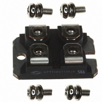
... SOT-227 (ISOTOP ® ) Package Outline W=4.1 (.161) W=4.3 (.169) H=4.8 (.187) H=4.9 (.193) (4 places) 4.0 (.157) 4.2 (.165) (2 places) 3.3 (.129) 3.6 (.143) * Emitter/Anode * Emitter/Anode Dimensions in Millimeters and (Inches ) APT150GT120JR 10% Gate Voltage T = 125° d(on) 90% t Collector Current r 5% 10% 5% Collector Voltage Switching Energy 11 ...