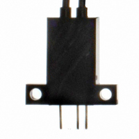
EE-SPZ401W-02 Omron, EE-SPZ401W-02 Datasheet - Page 10

EE-SPZ401W-02
Manufacturer Part Number
EE-SPZ401W-02
Description
OPTO SENSOR LIGHT-ON TRANS
Manufacturer
Omron
Datasheet
1.EE-SPZ401W-02.pdf
(13 pages)
Specifications of EE-SPZ401W-02
Sensing Distance
0.197" (5mm)
Sensing Method
Through-Beam
Output Configuration
NPN - Open Collector/Light-ON
Mounting Type
Screw Mount
Current - Supply
15mA
Voltage - Supply
5 V ~ 24 V
Package / Case
Module, Connector
Lead Free Status / RoHS Status
Contains lead / RoHS compliant by exemption
Response Time
-
Lead Free Status / RoHS Status
Contains lead / RoHS compliant by exemption, Lead free / RoHS Compliant
Other names
EESPZ401W02
Available stocks
Company
Part Number
Manufacturer
Quantity
Price
Company:
Part Number:
EE-SPZ401W-02
Manufacturer:
OMRON
Quantity:
1 000
<Countermeasures for Switching Power Supplies>
(1) Attach a capacitor of 10 μF min. to the wires as close as possible
(2) Connect to the 0-V line of the power source or connect to the
(3) Connect the noise filter terminal (neutral terminal to ACG) of the
<Countermeasures to Handle Inductive Noise>
(4) Insert a plastic insulator of approximately 10 mm between the
• Take either of the following countermeasures as required if
connecting a Photomicrosensor with Modulated Light to a switching
power supply.
The line connected as mentioned above should be
grounded or connected to the mounting base to
ensure stable operation. (Recommended by power
supply manufacturers.)
to the Photomicrosensor. (Use a capacitor with a dielectric
strength that is at least twice the Photomicrosensor's power
supply voltage. Do not use tantalum capacitors. A short-circuit
may cause the capacitor to ignite due to the large current flow.)
power source via a capacitor of approximately 0.47 μF to reduce
the impedance of the mounting base to prevent inductive noise
from entering the mounting base.
switching power supply to the case (FG) and 0-V terminal of the
power supply.
Sensor and the mounting base.
Mounting
base
Sensor
Mounting
base
Sensor
http://www.ia.omron.com/
OUT
To the
power supply
To the Sensor
(0.47 μF)
2 m max.
Capacitance
of 10 μF min.
12 to 24 VDC
C
ACG
+ V
FG
Grounding
0 V
0 V
G
Switching power supply
+ V
0 V
G
Extension cable
Switching
power supply
Input
Photomicrosensors Technical Guide
<Effects of Inductive Noise>
Precautions for Reflective Photomicrosensors
<Sensing Distance>
<Typical Example>
EE-SPY30/40 Series
<Background Objects>
• When there is inductive noise in the Sensor mounting frame
• The Reflective Photomicrosensor model is based on sensing a
• Use the Sensor only after carefully studying the possibility of light
(metal), the output of the Sensor may be affected. In this case,
ensure that there is no electrical potential difference between the
Sensor 0-V terminal and the Sensor mounting frame, or put a 0.47-
μF capacitor between the 0-V terminal and the frame.
sheet of white paper with a reflection factor of 90%. The sensing
distance varies with the other conditions of the objects being
detected.
entering the Sensor due to light being reflected off background
objects.
Decrease reflection from the background object, e.g., by providing
a sufficient distance to the background or by using a black sponge
as the background.
(c)Copyright OMRON Corporation 2008 All Rights Reserved.
15
10
5
0
Mounting frame
1
Sensing object
White paper
(reflection factor: 90%)
2
Sensor
L
2
2
L
Sensing object
3
2
5
0.47 μF
2
12 to 24 VDC
7
Sensing area L
0 V
2
Background object
10
2
20
Power
supply
2
2
30
(mm
2
50
2
2
)
C-4


