OPB917B TT Electronics/Optek Technology, OPB917B Datasheet
OPB917B
Specifications of OPB917B
Available stocks


Related parts for OPB917B


OPB917B Summary of contents
Page 1
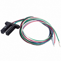
Prod uct Bul le tin OPB917 Feb ru ary 2001 Photologic Slotted Op ti cal Switches Type OPB917 Series Fea tures Choice of output configuration 24” min 26 AWG wires Low power consumption 0.86” (21.8 mm) deep slot De scrip ...
Page 2
... Line .90” Schematics OPB917B BUFFER WITH 10K PULL-UP RESISTOR Anode (Red) VREG AMP Cathode (Black) LIGHT ON - OUTPUT HIGH OPB917BOC BUFFER OPEN COLLECTOR Anode (Red) VREG AMP Cathode (Black) LIGHT ON - OUTPUT HIGH Optek Tech nol ogy, Inc. 1215 W. Crosby Road PART NUMBER GUIDE ...
Page 3
... OPB917B OPB917BOC V OL OPB917I OPB917IOC Low Level Output Voltage: OPB917B V OH OPB917I High Level Output Current: OPB917BOC I OH OPB917IOC LED Positive-Going Threshold Current: OPB917B and OPB917I I (+) F OPB917BOC and OPB917IOC I (+)/I (-) Hysteresis Rise Time, Fall Time r f Propagation Delay Low-High & ...