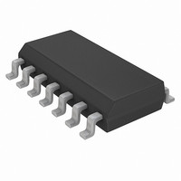
PIC16LF1824-I/SL Microchip Technology, PIC16LF1824-I/SL Datasheet - Page 21

PIC16LF1824-I/SL
Manufacturer Part Number
PIC16LF1824-I/SL
Description
IC PIC MCU 8BIT 14KB FLSH 14SOIC
Manufacturer
Microchip Technology
Series
PIC® XLP™ 16Fr
Specifications of PIC16LF1824-I/SL
Core Size
8-Bit
Program Memory Size
7KB (4K x 14)
Core Processor
PIC
Speed
32MHz
Connectivity
I²C, SPI, UART/USART
Peripherals
Brown-out Detect/Reset, POR, PWM, WDT
Number Of I /o
11
Program Memory Type
FLASH
Eeprom Size
256 x 8
Ram Size
256 x 8
Voltage - Supply (vcc/vdd)
1.8 V ~ 3.6 V
Data Converters
A/D 8x10b
Oscillator Type
Internal
Operating Temperature
-40°C ~ 85°C
Package / Case
14-SOIC (0.154", 3.90mm Width)
Controller Family/series
PIC16LF
No. Of I/o's
12
Eeprom Memory Size
256Byte
Ram Memory Size
256Byte
Cpu Speed
32MHz
No. Of Timers
5
Processor Series
PIC16LF
Core
PIC
3rd Party Development Tools
52715-96, 52716-328, 52717-734
Development Tools By Supplier
PG164130, DV164035, DV244005, DV164005
Lead Free Status / RoHS Status
Lead free / RoHS Compliant
Lead Free Status / RoHS Status
Lead free / RoHS Compliant, Lead free / RoHS Compliant
Available stocks
Company
Part Number
Manufacturer
Quantity
Price
Company:
Part Number:
PIC16LF1824-I/SL
Manufacturer:
MICROCHIP
Quantity:
2 920
Part Number:
PIC16LF1824-I/SL
Manufacturer:
MICROCHI
Quantity:
20 000
PIC16F/LF182X/PIC12F/LF1822
5.0
PROGRAMMING ALGORITHMS
The PIC12F1822/16F182X devices use internal
latches to temporarily store the 14-bit words used for
programming. Refer to Table 4-2 for specific latch in
formation. The data latches allow the user to write the
program words with a single Begin Externally Timed
Programming or Begin Internally Timed Programming
command. The Load Program Data or the Load Config-
uration command is used to load a single data latch.
The data latch will hold the data until the Begin Exter-
nally Timed Programming or Begin Internally Timed
Programming command is given.
The data latches are aligned with the LSbs of the
address. The PC’s address at the time the Begin
Externally Timed Programming or Begin Internally
Timed Programming command is given will determine
which location(s) in memory are written. Writes cannot
cross the physical boundary. For example, with the
PIC16F1827, attempting to write from address 0002h-
0009h will result in data being written to 0008h-000Fh.
If more than the maximum number of data latches are
written without a Begin Externally Timed Programming
or Begin Internally Timed Programming command, the
data in the data latches will be overwritten. The
following figures show the recommended flowcharts for
programming.
Advance Information
2010 Microchip Technology Inc.
DS41390C-page 21


