AD7298BCPZ Analog Devices Inc, AD7298BCPZ Datasheet - Page 20
AD7298BCPZ
Manufacturer Part Number
AD7298BCPZ
Description
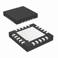
IC ADC 12BIT SPI/SRL 1M 20LFCSP
Manufacturer
Analog Devices Inc
Datasheet
1.AD7298BCPZ.pdf
(24 pages)
Specifications of AD7298BCPZ
Data Interface
Serial, SPI™
Featured Product
AD7298 ADC with Temperature Sensor
Number Of Bits
12
Sampling Rate (per Second)
1M
Number Of Converters
1
Power Dissipation (max)
22.7mW
Voltage Supply Source
Single Supply
Operating Temperature
-40°C ~ 125°C
Mounting Type
Surface Mount
Package / Case
20-WFQFN, CSP Exposed Pad
Resolution (bits)
12bit
Sampling Rate
1MSPS
Input Channel Type
Single Ended
Supply Voltage Range - Digital
1.65V To 3.6V
Supply Current
5.8mA
Digital Ic Case
RoHS Compliant
Supply Voltage Range - Analog
1.65V To 3.6V
Digital Ic Case Style
LFCSP
Rohs Compliant
Yes
Lead Free Status / RoHS Status
Lead free / RoHS Compliant
Available stocks
Company
Part Number
Manufacturer
Quantity
Price
Company:

Part Number:
AD7298BCPZ
Manufacturer:
Analog Devices Inc
Quantity:
135
Part Number:
AD7298BCPZ
Manufacturer:
ADI/亚德诺
Quantity:
20 000


AD7298
Full Power-Down Mode
In this mode, all internal circuitry on the AD7298 is powered
down and no information is retained in the control register or any
other internal register. If the averaging feature for the tempera-
ture sensor is enabled in the control register (T
averaging is reset once the device enters power-down mode.
The AD7298 is placed into full power-down mode by bringing
the logic level on the PD / RST pin low for greater than 100 ns.
When placing the AD7298 in full power-down mode, the ADC
inputs must return to 0 V. The PD / RST pin is asynchronous to
the clock, thus it can be triggered at any time. The part can be
powered up for normal operation by bringing the PD / RST pin
logic level back to a high logic state.
The full power-down feature can be used to reduce the average
power consumed by the AD7298 when operating at lower
throughput rates. The user should ensure that t
elapsed prior to programming the control register and initiating
a valid conversion.
POWERING UP THE AD7298
The AD7298 contains a power-on reset circuit, which sets
the control register to its default setting of all zeros, thus the
internal reference is enabled and the device is configured for the
normal mode of operation. On power-up, the internal reference
is by default enabled, which takes up 6 ms (maximum) to
power-up.
SENSE
POWER_UP
AVG), the
has
Rev. A | Page 20 of 24
If an external reference is being used, the user does not need to
wait for the internal reference to power-up fully. The AD7298
digital interface is fully functional after 500 µs from initial
power-up. Therefore, the user can write to the control register
after 500 µs to switch to external reference mode. The AD7298
is then immediately ready to convert once the external reference
is available on the V
When supplies are first applied to the AD7298, the user must
wait the specified 500 µs before programming the control
register to select the desired channels for conversion.
RESET
The AD7298 includes a reset feature, that can be used to reset
the device and the contents of all internal registers, including
the control register, to their default state.
To activate the reset operation, the PD / RST pin should be
brought low for no longer than 100 ns. It is asynchronous with
the clock, thus it can be triggered at any time. If the PD / RST pin
is held low for greater than 100 ns, the part enters full power-
down mode. It is imperative that the PD / RST pin be held at a
stable logic level at all times to ensure normal operation.
REF
pin.
Related parts for AD7298BCPZ
Image
Part Number
Description
Manufacturer
Datasheet
Request
R

Part Number:
Description:
8Channel 10Bit SAR
Manufacturer:
Analog Devices Inc
Datasheet:

Part Number:
Description:
±1.7g Dual-Axis IMEMS Accelerometer Evaluation Board
Manufacturer:
Analog Devices Inc
Datasheet:

Part Number:
Description:
Inertial Sensor Evaluation System
Manufacturer:
Analog Devices Inc
Datasheet:
Part Number:
Description:
Manufacturer:
Analog Devices Inc
Datasheet:
Part Number:
Description:
Manufacturer:
Analog Devices Inc
Datasheet:
Part Number:
Description:
Manufacturer:
Analog Devices Inc
Datasheet:
Part Number:
Description:
Manufacturer:
Analog Devices Inc
Datasheet:
Part Number:
Description:
Manufacturer:
Analog Devices Inc
Datasheet:
Part Number:
Description:
Manufacturer:
Analog Devices Inc
Datasheet:
Part Number:
Description:
Manufacturer:
Analog Devices Inc
Datasheet:
Part Number:
Description:
Manufacturer:
Analog Devices Inc
Datasheet:
Part Number:
Description:
Manufacturer:
Analog Devices Inc
Datasheet: