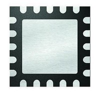
MCP4461T-502E/ML Microchip Technology, MCP4461T-502E/ML Datasheet - Page 73

MCP4461T-502E/ML
Manufacturer Part Number
MCP4461T-502E/ML
Description
IC DGTL POT 257TAPS 5K 20QFN
Manufacturer
Microchip Technology
Datasheet
1.MCP4441-103EML.pdf
(100 pages)
Specifications of MCP4461T-502E/ML
Package / Case
20-VFQFN Exposed Pad
Temperature Coefficient
150 ppm/°C Typical
Taps
257
Resistance (ohms)
5K
Number Of Circuits
4
Memory Type
Non-Volatile
Interface
I²C, 2-Wire Serial
Voltage - Supply
2.7 V ~ 5.5 V
Operating Temperature
-40°C ~ 125°C
Mounting Type
Surface Mount
Number Of Pots
Quad
Taps Per Pot
257
Resistance
5 KOhms
Wiper Memory
Non Volatile
Buffered Wiper
Buffered
Digital Interface
I2C
Operating Supply Voltage
2.7 V to 5.5 V
Supply Current
600 uA
Maximum Operating Temperature
+ 125 C
Minimum Operating Temperature
- 40 C
Description/function
Quad I2C Digital POT with Nonvolatile Memory
Mounting Style
SMD/SMT
Supply Voltage (max)
5.5 V
Supply Voltage (min)
2.7 V
Lead Free Status / RoHS Status
Lead free / RoHS Compliant
8.0
Nonvolatile digital potentiometers have a multitude of
practical uses in modern electronic circuits. The most
popular uses include precision calibration of set point
thresholds, sensor trimming, LCD bias trimming, audio
attenuation, adjustable power supplies, motor control
overcurrent trip setting, adjustable gain amplifiers and
offset trimming. The MCP44XX devices can be used to
replace
applications where the operating and terminal voltages
are within CMOS process limitations (V
5.5V).
8.1
The circuit in
TC1240A doubling charge pump. When the SHDN pin
is high, the TC1240A is off, and the level on the HVC/
A0 pin is controlled by the PIC® microcontrollers
(MCUs) IO2 pin.
When the SHDN pin is low, the TC1240A is on and the
V
HVC/A0 pin to go higher than the voltage such that the
PIC MCU’s IO2 pin “clamps” at approximately V
FIGURE 8-1:
Generate the V
© 2010 Microchip Technology Inc.
OUT
PIC MCU
voltage is 2 * V
APPLICATIONS EXAMPLES
Techniques to Force the HVC/A0
Pin to V
IO1
IO2
the
Figure 8-1
common
IHH
IHH
Voltage.
R
Using the TC1240A to
DD
1
SHDN
V
. The resistor R
TC1240A
IN
shows a method using the
mechanical
V
OUT
HVC/A0
C
C+
2
C-
trim
DD
MCP4XXX
1
allows the
= 2.7V to
C
pot
DD
1
.
in
The circuit in
MCP402X Nonvolatile Digital Potentiometer Evaluation
Board (Part Number: MCP402XEV). This method
requires that the system voltage be approximately 5V.
This ensures that when the PIC10F206 enters a brown-
out condition, there is an insufficient voltage level on
the HVC/A0 pin to change the stored value of the wiper.
The MCP402X Nonvolatile Digital Potentiometer Eval-
uation Board User’s Guide (DS51546) contains a
complete schematic.
GP0 is a general purpose I/O pin, while GP2 can either
be a general purpose I/O pin or it can output the internal
clock.
For the serial commands, configure the GP2 pin as an
input (high impedance). The output state of the GP0 pin
will determine the voltage on the HVC/A0 pin (V
V
For high-voltage serial commands, force the GP0
output pin to output a high level (V
GP2 pin to output the internal clock. This will form a
charge pump and increase the voltage on the CS pin
(when the system voltage is approximately 5V).
FIGURE 8-2:
Digital Potentiometer Evaluation Board
(MCP402XEV) implementation to generate the
V
IH
IHH
PIC10F206
).
voltage.
GP0
GP2
Figure 8-2
MCP444X/446X
C
1
MCP4XXX Nonvolatile
shows the method used on the
R
1
OH
) and configure the
DS22265A-page 73
C
2
HVC/A0
MCP4XXX
IL
or


