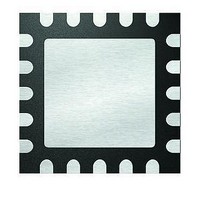
MCP4461T-502E/ML Microchip Technology, MCP4461T-502E/ML Datasheet - Page 94

MCP4461T-502E/ML
Manufacturer Part Number
MCP4461T-502E/ML
Description
IC DGTL POT 257TAPS 5K 20QFN
Manufacturer
Microchip Technology
Datasheet
1.MCP4441-103EML.pdf
(100 pages)
Specifications of MCP4461T-502E/ML
Package / Case
20-VFQFN Exposed Pad
Temperature Coefficient
150 ppm/°C Typical
Taps
257
Resistance (ohms)
5K
Number Of Circuits
4
Memory Type
Non-Volatile
Interface
I²C, 2-Wire Serial
Voltage - Supply
2.7 V ~ 5.5 V
Operating Temperature
-40°C ~ 125°C
Mounting Type
Surface Mount
Number Of Pots
Quad
Taps Per Pot
257
Resistance
5 KOhms
Wiper Memory
Non Volatile
Buffered Wiper
Buffered
Digital Interface
I2C
Operating Supply Voltage
2.7 V to 5.5 V
Supply Current
600 uA
Maximum Operating Temperature
+ 125 C
Minimum Operating Temperature
- 40 C
Description/function
Quad I2C Digital POT with Nonvolatile Memory
Mounting Style
SMD/SMT
Supply Voltage (max)
5.5 V
Supply Voltage (min)
2.7 V
Lead Free Status / RoHS Status
Lead free / RoHS Compliant
MCP444X/446X
Using the simulation models of the NMOS and PMOS
devices for the MCP44XX analog switch
we plot the device resistance when the devices are
turned on.
resistances of the NMOS and PMOS devices as the
V
simply the parallel resistance on the NMOS and PMOS
devices (R
voltage for the NMOS ad PMOS devices, the
resistance becomes very large (Gigaohms). In the
transistors active region, the resistance is much lower.
For these graphs, the resistances are on different
scales.
NMOS and PMOS device resistance for their active
region and the resulting wiper resistance. For these
graphs, all resistances are on the same scale.
FIGURE B-10:
FIGURE B-11:
Transistor Resistance (R
Wiper Resistance (R
(V
DS22265A-page 94
IN
DD
voltage is increased. The wiper resistance (R
V
= 3.0V).
IN
3.00E+10
2.50E+10
2.00E+10
1.50E+10
1.00E+10
5.00E+09
0.00E+00
Figure B-13
W
Figure B-11
0.0
= R
“gate”
“gate”
R
PMOS
Theshold
PMOS
NMOS
0.3
R
and
Analog Switch.
NMOS and PMOS
W
W
|| R
NMOS
0.6
PMOS
) VS. V
V
and
IN
PMOS
Figure B-14
NMOS
Voltage
R
0.9
W
Figure B-12
R
). Below the threshold
NMOS
IN
1.2
, R
V
G
NMOS
Theshold
PMOS
(V
1.5
DD
(Figure
only plot the
V
/V
) and
OUT
1.8
show the
SS
2500
2000
1500
1000
500
0
)
B-10),
W
) is
FIGURE B-12:
Transistor Resistance (R
Wiper Resistance (R
(V
FIGURE B-13:
Transistor Resistance (R
Wiper Resistance (R
(V
FIGURE B-14:
Transistor Resistance (R
Wiper Resistance (R
(V
DD
DD
DD
= 1.8V).
= 3.0V).
= 1.8V).
7.00E+09
6.00E+09
5.00E+09
4.00E+09
3.00E+09
2.00E+09
1.00E+09
0.00E+00
300
250
200
150
100
5000
4500
4000
3500
3000
2500
2000
1500
1000
50
500
0
0
0.0
0.0
0.0
R
0.3
R
0.6
NMOS
PMOS
R
0.6
NMOS
0.6
NMOS and PMOS
NMOS and PMOS
NMOS and PMOS
W
W
W
© 2010 Microchip Technology Inc.
PMOS
Theshold
1.2
R
) VS. V
) VS. V
) VS. V
V
V
1.2
V
W
IN
IN
IN
NMOS
NMOS
NMOS
Voltage
Voltage
Voltage
0.9
NMOS
Theshold
R
1.8
1.8
W
IN
IN
IN
R
R
R
, R
, R
, R
W
PMOS
NMOS
1.2
R
PMOS
PMOS
PMOS
PMOS
2.4
2.4
1.5
) and
) and
) and
3.0
160
140
120
100
80
60
40
20
0
3.0
1.8


