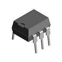
TCDT1122G Vishay, TCDT1122G Datasheet - Page 5

TCDT1122G
Manufacturer Part Number
TCDT1122G
Description
Transistor Output Optocouplers Phototransistor Out Single CTR > 63-125%
Manufacturer
Vishay
Specifications of TCDT1122G
Maximum Input Diode Current
60 mA
Maximum Reverse Diode Voltage
5 V
Output Device
Transistor
Output Type
DC
Configuration
1
Input Type
DC
Maximum Collector Emitter Voltage
90 V
Maximum Collector Emitter Saturation Voltage
300 mV
Isolation Voltage
5300 Vrms
Current Transfer Ratio
125 %
Maximum Forward Diode Voltage
1.6 V
Maximum Collector Current
50 mA
Maximum Power Dissipation
250 mW
Maximum Operating Temperature
+ 100 C
Minimum Operating Temperature
- 55 C
Package / Case
PDIP-6
No. Of Channels
1
Optocoupler Output Type
Phototransistor
Input Current
50mA
Output Voltage
70V
Opto Case Style
DIP
No. Of Pins
6
Approval Bodies
UL
Rohs Compliant
Yes
Lead Free Status / RoHS Status
Lead free / RoHS Compliant
Available stocks
Company
Part Number
Manufacturer
Quantity
Price
Company:
Part Number:
TCDT1122G
Manufacturer:
OMRON
Quantity:
5 510
Part Number:
TCDT1122G
Manufacturer:
N/A
Quantity:
20 000
Typical Characteristics (Tamb = 25 °C unless otherwise specified)
Document Number 83532
Rev. 1.6, 26-Oct-04
t
t
t
t
p
d
r
on
96 1 1700
96 11862
(= t
Figure 4. Total Power Dissipation vs. Ambient Temperature
100%
10%
90%
d
1000
300
250
200
150
100
100
+ t
I
I
0.1
50
C
10
F
0
0
0
r
1
)
Figure 5. Forward Current vs. Forward Voltage
0
0 0.2 0.4 0.6 0.8 1.0 1.2 1.4 1.6 1.8 2.0
Phototransistor
IR-diode
Coupled device
t
pulse duration
delay time
rise time
turn-on time
d
t
on
T
t
amb
r
V
F
Figure 3. Switching Times
– Ambient T emperature( °C )
- Forward Voltage ( V )
t
40
p
t
t
t
t
s
f
off
s
(= t
80
s
t
off
+ t
t
f
f
)
storage time
fall time
turn-off time
96 11698
120
t
t
96 11918
95 11038
95 11040
TCDT1120/ TCDT1120G
Figure 7. Collector Dark Current vs. Ambient Temperature
10000
1000
Figure 6. Relative Current Transfer Ratio vs. Ambient
0.01
100
100
1.5
1.4
1.3
1.2
1.1
1.0
0.9
0.8
0.7
0.6
0.5
0.1
10
10
1
1
Figure 8. Collector Current vs. Forward Current
–30 –20 –10 0 10 20 30 40 50 60 70 80
0.1
0
V
V
I
CE
F
CE
=10mA
V
I
F
=5V
T
T
CE
=5V
=0
amb
amb
=30V
25
I
F
– Ambient Temperature (°C )
– Ambient Temperature ( °C )
– Forward Current ( mA )
1
Temperature
Vishay Semiconductors
50
10
75
100
100
www.vishay.com
5


