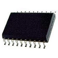
KX1400EW Keterex, KX1400EW Datasheet - Page 15

KX1400EW
Manufacturer Part Number
KX1400EW
Description
Audio D/A Converter ICs KX1400 Audio Playback IC
Manufacturer
Keterex
Datasheet
1.KX1400EW.pdf
(29 pages)
Specifications of KX1400EW
Resolution
12 bit
Operating Supply Voltage
2.7 V to 5.5 V
Operating Temperature Range
- 40 C to + 85 C
Maximum Power Dissipation
120 mW
Mounting Style
SMD/SMT
Number Of Dac Outputs
2
Power Consumption
320 mW
Supply Current
50 mA
Thd Plus Noise
40 dB
Package / Case
SOIC-20
Lead Free Status / RoHS Status
Lead free / RoHS Compliant
of data. Some opcodes do not require a data argument but a data field is always required to ensure the
entire command word is 8 bits or 16 bits wide. In these cases, the value of the data field is ignored, and
therefore may be set to any convenient value. Commands are sent to the MCU interface by transmitting
the command into the shift register most-significant-bit (MSB) first. The opcode is the 2 or 4 least-
significant bits (LSBs) of the command word and is therefore sent last. Figure 6.5 illustrates the format of
a typical 16-bit command.
SYMBOL
t
t
t
t
t
t
t
t
t
t
t
t
6.4.2. Host MCU Command Format
Host MCU commands are either 8 or 16-bits long and consist of a 2 or 4-bit opcode and 4, 12, or 14 bits
6.5. Digital Audio Processor
The on-chip Digital Audio Processor incorporates an audio data decoder and 12-bit delta-sigma
modulator. It supports audio data sampled at 8 kHz and encoded in the IMA ADPCM or 12-bit PCM (2’s-
complement, uncompressed) formats. Oversampling and second-order noise shaping techniques are
employed to ensure quantization noise generated by the delta-sigma modulator is suppressed within the
audio band.
The output signal is an enhanced, 256 kHz pulse-width-modulation representation of the audio signal.
The switching frequency of this signal is well beyond the audio range and therefore requires only minimal
low-pass filtering.
eliminating the need for additional filtering.
RCS
BCS
RDYH
BSYH
CKSU
CKSU
CKH
CKL
CSH
CSHD
SDISU
SDIH
First Bit
Transmitted
Bit
15
Bit
14
RDY
BUSY Falling Edge to CS
CS
CS
CS
state
CS
SCL High Time
SCL Low Time
CS
CS
SDI Valid to SCL Rising Edge
SDI Valid Hold Time
¯¯ to
¯¯ to
¯¯
¯¯
¯¯
¯¯
¯¯¯
to First SCL Rising Edge Time when not in stand-by
to First SCL Rising Edge Time when in stand-by state
High Time
Hold Time
Bit
13
to
BUSY
RDY
¯¯¯
CS
¯¯ Setup Time
Bit
12
High Time
Typically, the response characteristics of the external speaker are sufficient,
High Time
Bit
11
Figure 6.5. Example of a 16-bit Command
Table 6.5. Host MCU Interface Timing
¯¯
PARAMETER
Bit
10
Data
Setup Time
Bit
9
Bit
8
Bit
7
Bit
KX1400 Audio Playback IC
6
Bit
5
Bit
4
MIN
150
500
150
150
150
50
50
0
0
0
Bit
3
MAX
Bit
500
625
Opcode
2
Transmitted
Bit
1
UNITS
Last Bit
ns
ns
ns
ns
ns
ns
ns
ns
ns
ns
ns
ns
Bit
0
15


