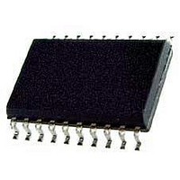
KX1400EW Keterex, KX1400EW Datasheet - Page 26

KX1400EW
Manufacturer Part Number
KX1400EW
Description
Audio D/A Converter ICs KX1400 Audio Playback IC
Manufacturer
Keterex
Datasheet
1.KX1400EW.pdf
(29 pages)
Specifications of KX1400EW
Resolution
12 bit
Operating Supply Voltage
2.7 V to 5.5 V
Operating Temperature Range
- 40 C to + 85 C
Maximum Power Dissipation
120 mW
Mounting Style
SMD/SMT
Number Of Dac Outputs
2
Power Consumption
320 mW
Supply Current
50 mA
Thd Plus Noise
40 dB
Package / Case
SOIC-20
Lead Free Status / RoHS Status
Lead free / RoHS Compliant
KX1400 Audio Playback IC
Description: The Set Outputs command sets the state of the two general purpose output pins.
8.10. Play ADPCM (From MCU)
Description: When issued from the host MCU interface, the Play ADPCM command sends two 4-bit, 8
26
Encoding:
Options: None
Options: Bit 4: ADPCM Reset
Length: 8 Bits
Type: Control
Type: Audio
Data: Bit 4: Reserved
Data: Bits 11-8: ADPCM Sample 1
The output drivers for the general purpose output pins may be configured as open-drain or
push-pull. The default configuration after a device reset is both outputs set to logic level
low with push-pull drive characteristics.
This bit is reserved and should always be set to logic zero. Behavior when setting this bit
to logic one is undefined.
Bits 7-5: Outputs Configuration
Specifies the output driver characteristics and levels for the two general purpose output
pins.
kHz IMA ADPCM audio samples to the KX1400 audio processor. This command can be
repeated with new data to stream a continuous ADPCM audio sequence to the KX1400 in
real time. If a new Play ADPCM or other audio command is not issued within two sample
periods (250 µs) of the previous command, the speaker output level will be maintained at
its last level, in effect silencing the output.
Setting this bit to a logic one resets the ADPCM decoder state. The ADPCM decoder must
be reset at the beginning of each new ADPCM sequence. Therefore, this bit should be set
when the command is issued with the first two samples in the sequence and then cleared in
all subsequent commands until a new sequence is started.
This is a 4-bit, 8 kHz IMA ADPCM audio sample. Sample 1 is processed before Sample 2.
Bits 15-12: ADPCM Sample 2
ADPCM Sample 2
Bits 7-5
X00
L01
L10
L11
Bits 15-12
X = 0: output drivers are push-pull, X= 1: output drivers are open-drain
Sets GPO1 output level to L (0 = logic low, 1 = logic high)
Sets GPO2 output level to L (0 = logic low, 1 = logic high)
Sets GPO1 and GPO2 output levels to L (0 = logic low, 1 = logic high)
ADPCM Sample 1
Bits 11-8
Outputs State
Bits 7-5
Unused
ADPCM Reset
Bit 4
Bits 3-0
1010


