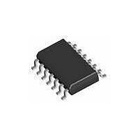
1286S14-U THAT Corporation, 1286S14-U Datasheet

1286S14-U
Specifications of 1286S14-U
Related parts for 1286S14-U
1286S14-U Summary of contents
Page 1
... THAT1283 -3 dB THAT1286 -6 dB Figure 1. Equivalent circuit THAT Corporation; 45 Sumner Street; Milford, MA 01757-1656; USA Tel: +1 508 478 9200; Fax: +1 508 478 0990; Web: www.thatcorp.com Copyright © 2007, THAT Corporation • Balanced Audio Line Receivers • Instrumentation Amplifiers • Differential Amplifiers • ...
Page 2
... While specific resistor ratios are very closely trimmed, absolute resistance values can vary ±25% from the typical values show n. Input impedance is monitored by lot sampling. 6. Defined with respect to differential gain. 7. Parameter guaranteed over the entire range of power supply and temperature. THAT Corporation; 45 Sumner Street; Milford, MA 01757-1656; USA Tel: +1 508 478 9200; Fax: +1 508 478 0990; Web: www.thatcorp.com Page SPECIFICATIONS ...
Page 3
... IN(DIFF) ½v IN(DIFF IN(CM) Figure 2. Simplified test circuit (1/2 of 128x shown) THAT Corporation; 45 Sumner Street; Milford, MA 01757-1656; USA Tel: +1 508 478 9200; Fax: +1 508 478 0990; Web: www.thatcorp.com Page Conditions R = 2kΩ 1280 (0dB gain) 1283 (-3dB gain) 1286 (-6dB gain 2kΩ ...
Page 4
... Figure 3. Representative input protection circuit THAT Corporation; 45 Sumner Street; Milford, MA 01757-1656; USA Tel: +1 508 478 9200; Fax: +1 508 478 0990; Web: www.thatcorp.com Page Theory of Operation A further consideration is that after trimming, the two resistor divider ratios are tightly controlled, but the actual value of any individual resistor is not. ...
Page 5
... So, we must consider the inputs of the opamp. For common-mode signals (V ), the common-mode IN(CM) input current splits to flow through both R THAT Corporation; 45 Sumner Street; Milford, MA 01757-1656; USA Tel: +1 508 478 9200; Fax: +1 508 478 0990; Web: www.thatcorp.com Page Because v ...
Page 6
... With ±15 V supply rails, the maximum output signal swing is ~+21.1 dBu; here the maximum gain. In THAT Corporation; 45 Sumner Street; Milford, MA 01757-1656; USA Tel: +1 508 478 9200; Fax: +1 508 478 0990; Web: www.thatcorp.com Page each case, a 1283 configured for -3 dB gain is the ideal choice ...
Page 7
... In+ Ref Figure line receiver THAT Corporation; 45 Sumner Street; Milford, MA 01757-1656; USA Tel: +1 508 478 9200; Fax: +1 508 478 0990; Web: www.thatcorp.com Page Applications Instrumentation Amplifier Application Figure 11 shows one half of a 1280 configured as an instrumentation amplifier. The two opamps preceding the 1280 buffer the input signal before However, their passing the 1280 ...
Page 8
... U2B V OP-270 EE Figure 11. Instrumentation amplifier THAT Corporation; 45 Sumner Street; Milford, MA 01757-1656; USA Tel: +1 508 478 9200; Fax: +1 508 478 0990; Web: www.thatcorp.com Page this signal down by 18.8 dB while attenuating the noise of the line receivers as well. In ADC applications such as this, noise is This usually a significant consideration ...
Page 9
... Ref 5 In+ 10n V- U1B 8 4 1283 V EE Control Voltage 2 6.2mV/dB Figure 13. Voltage-controlled gain control of a balanced signal THAT Corporation; 45 Sumner Street; Milford, MA 01757-1656; USA Tel: +1 508 478 9200; Fax: +1 508 478 0990; Web: www.thatcorp.com Page -18 In- Sense 13 R1 Vout 909R 3 Ref ...
Page 10
... Complies with January 27, 2003 RoHS requirements Above-referenced JEDEC soldering profile Gain Copyright © 2007, THAT Corporation THAT 1280 Series Dual Balanced Line Receiver ICs Min Typ Max Units 14 Pin SO 100 ºC/W JEDEC JESD22-A113-D (250 ºC) 1 Order Number 1280S14-U 1283S14-U 1286S14-U Table 2. Ordering information ...


