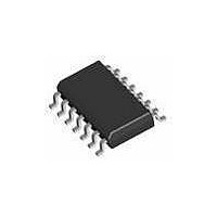
1286S14-U THAT Corporation, 1286S14-U Datasheet - Page 7

1286S14-U
Manufacturer Part Number
1286S14-U
Description
Buffers & Line Drivers Dual Bal. Line Receiver -6 db
Manufacturer
THAT Corporation
Datasheet
1.1286S14-U.pdf
(10 pages)
Specifications of 1286S14-U
Supply Voltage (max)
36 V
Supply Voltage (min)
6 V
Maximum Operating Temperature
+ 85 C
Mounting Style
SMD/SMT
Minimum Operating Temperature
- 40 C
Output Current
+/- 42 mA
Output Voltage
+/- 0.5 V
Supply Current
6 mA
Logic Type
Differential Line Receiver
Package / Case
SOIC-14
Lead Free Status / RoHS Status
Lead free / RoHS Compliant
THAT 1280 Series
Dual Balanced Line Receiver ICs
thought of as precision differential amplifiers with
gains of zero, -3 and -6 dB respectively. These
devices are primarily intended as balanced line
receivers for audio applications.
topology lends itself to other applications as well.
Basic Balanced Receiver Applications
1286 and 1286 configured as zero, -3 dB, and -6 dB
line receivers. Figures 8 and 9, respectively, show
the 1283 and 1286 configured as +3 dB and +6 dB
line receivers. The higher gains are achieved by
swapping the positions of the resistors within each
pair in regard to signal input vs. Output.
Precision Summing Application
sion summing amplifier. This circuit uses both the
In+ and Ref pins as inputs. Because of the excellent
matching between the laser-trimmed resistor pairs,
the output voltage is precisely equal to the sum of the
two input voltages.
In-
In+
In-
In+
The THAT 1280, 1283, and 1286 are usually
Figures 5, 6, and 7, respectively, show the 1280,
Figure 10 shows a 1280 configured as a preci-
2/6
3/5
2/6
3/5
In+
In-
In-
In+
Figure 5. Zero dB line receiver
Figure 6. -3 dB line receiver
10.5k
10.5k
9k
9k
11
11
4
4
V
V
V
V
CC
EE
Tel: +1 508 478 9200; Fax: +1 508 478 0990; Web: www.thatcorp.com
CC
EE
THAT Corporation; 45 Sumner Street; Milford, MA 01757-1656; USA
7.5k
7.5k
9k
9k
Sense
Sense
U1
1280
Vout
U1
1283
Vout
Ref
Ref
However, their
12/10
13/9
14/8
12/10
13/9
14/8
Copyright © 2007, THAT Corporation
Output
Output
Applications
Page 7 of 10
Instrumentation Amplifier Application
as an instrumentation amplifier. The two opamps
preceding the 1280 buffer the input signal before
passing it on to the 1280. The OP270 shown was
chosen for its combination of good ac and dc
performance.
provide gain equal to 1+(9.98 kΩ / R
signals, but unity gain for common-mode signals.
The 1280 then rejects the common mode signal while
passing on the differential portion.
opamps buffer the input of the 1280, raising the
circuit’s input impedance to both differential and
common-mode signals.
common-mode rejection less sensitive to variations
in the source impedance driving the stage.
THAT’s InGenius
to increase common-mode input impedance. This
even further inproves common-mode rejection in
real-world applications. See the THAT 1200-series
datasheet for more information.
In+
In-
In+
In-
Figure 11 shows one half of a 1280 configured
As noted in the Theory of Operation section,
3/5
2/6
In-
In+
2/6
3/5
Figure 8. +3 dB line receiver
Figure 7. -6 dB line receiver
In-
In+
12k
12k
In this configuration, the opamps
®
10.5k
10.5k
input stages use patented circuitry
11
4
V
V
11
CC
EE
4
V
V
CC
EE
This makes the circuit’s
Document 600114 Rev 01
6k
6k
7.5k
7.5k
Sense
U1
1286
Vout
Sense
U1
1283
Vout
Ref
Ref
g
) for differential
12/10
13/9
12/10
13/9
14/8
14/8
As well, the
Output
Out


