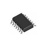
1286S14-U THAT Corporation, 1286S14-U Datasheet - Page 2

1286S14-U
Manufacturer Part Number
1286S14-U
Description
Buffers & Line Drivers Dual Bal. Line Receiver -6 db
Manufacturer
THAT Corporation
Datasheet
1.1286S14-U.pdf
(10 pages)
Specifications of 1286S14-U
Supply Voltage (max)
36 V
Supply Voltage (min)
6 V
Maximum Operating Temperature
+ 85 C
Mounting Style
SMD/SMT
Minimum Operating Temperature
- 40 C
Output Current
+/- 42 mA
Output Voltage
+/- 0.5 V
Supply Current
6 mA
Logic Type
Differential Line Receiver
Package / Case
SOIC-14
Lead Free Status / RoHS Status
Lead free / RoHS Compliant
Document 600114 Rev 01
1. All specifications are subject to change without notice.
2. Unless otherwise noted, T
3. Stresses above those listed under “Absolute Maximum Ratings” may cause permanent damage to the device. These are stress ratings only; the functional operation of
the device at these or any other conditions above those indicated in the operational sections of this specification is not impli ed. Exposure to absolute maximum rating condi-
tions for extended periods may affect device reliability.
4. 0 dBu = 0.775 Vrms.
5. While specific resistor ratios are very closely trimmed, absolute resistance values can vary ±25% from the typical values show n. Input impedance is
monitored by lot sampling.
6. Defined with respect to differential gain.
7. Parameter guaranteed over the entire range of power supply and temperature.
Supply Voltages (V
Maximum In
Max/Min Ref or Sense Voltage
Maximum Output Voltage (V
Parameter
Supply Current
Supply Voltage
Input Voltage Range
Input Impedance
Common Mode Rejection Ratio CMRR
Power Supply Rejection Ratio
Total Harmonic Distortion
Output Noise
Slew Rate
-
or In
5
+
CC
Voltage
- V
A
=25ºC, V
EE
Tel: +1 508 478 9200; Fax: +1 508 478 0990; Web: www.thatcorp.com
)
THAT Corporation; 45 Sumner Street; Milford, MA 01757-1656; USA
OM
CC
6
)
=+15V, V
Symbol
V
I
V
Z
PSRR
CC
V
Z
CC
THD
e
IN-DIFF
IN-DIFF
SR
IN-CM
Absolute Maximum Ratings
IN-CM
; -I
OUT
-V
-50V + V
V
V
EE
Electrical Characteristics
CC
CC
EE
EE
= -15V.
+ 0.5V, V
+ 0.5V, V
V
Copyright © 2007, THAT Corporation
Matched source impedances; V
out
CC
Differential (equal and opposite swing)
SPECIFICATIONS
= 5Vrms, f = 1kHz, BW = 22kHz, R
, 50V + V
±3V to ±18V; V
R
EE
EE
L
22 Hz to 22kHz bandwidth
= 2kΩ; C
- 0.5V
- 0.5V
40V
1283 (-3dB gain)
1286 (-6dB gain)
1283 (-3dB gain)
1286 (-6dB gain)
1283 (-3dB gain)
1286 (-6dB gain)
1283 (-3dB gain)
1286 (-6dB gain)
EE
1280 (0dB gain)
1280 (0dB gain)
1280 (0dB gain)
1280 (0dB gain)
Page 2 of 10
Common Mode
Common Mode
All versions
Differential
Conditions
No signal
L
20kHz
60Hz
= 300 pF, all gains
DC
CC
= -V
Storage Temperature Range (T
Operating Temperature Range (T
Output Short-Circuit Duration (t
Junction Temperature (T
EE
; all gains
CM
= ±10V
1
L
= 2 kΩ
2,4
2,3
10.5
Min
70
70
—
—
—
—
—
—
—
—
—
—
—
—
—
—
—
—
—
6
J
)
Dual Balanced Line Receiver ICs
0.0006
-104.5
-105.9
-107.3
21.5
24.5
27.5
27.5
29.1
Typ
—
31
18
21
24
18
90
90
85
90
15
6
SH
ST
)
)
OP
)
Max
36
—
—
—
—
—
—
—
—
—
—
—
—
—
—
—
—
—
—
—
8
THAT 1280 Series
-40 to +125 ºC
-40 to +85 ºC
Continuous
+125 ºC
Units
V/μs
dBu
dBu
dBu
dBu
dBu
dBu
dBu
dBu
dBu
mA
kΩ
kΩ
kΩ
kΩ
dB
dB
dB
dB
%
V


