ST10-Si-NN Applied Motion, ST10-Si-NN Datasheet - Page 2
ST10-Si-NN
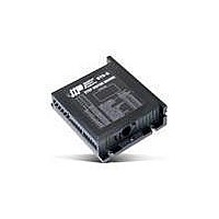
Manufacturer Part Number
ST10-Si-NN
Description
Stepper Drives 10A, Si-Control Programmer w/Config.
Manufacturer
Applied Motion
Datasheet
1.ST10-SI-NN.pdf
(4 pages)
Specifications of ST10-Si-NN
Current Type
Output
Motor Drive Type
Stepper
Supply Voltage
24 V to 80 V
Steps Resolution Per Revolution
200 to 51200
Lead Free Status / RoHS Status
Lead free / RoHS Compliant


2
SPECIFICATIONS
OUTPUT CURRENT
POWER SUPPLY
PROTECTION
IDLE CURRENT REDUCTION
MICROSTEP RESOLUTION
MICROSTEP EMULATION
ANTI-RESONANCE
(Electronic Damping)
TORQUE RIPPLE SMOOTHING
MODES OF OPERATION
INPUTS/OUTPUTS: ST-S, ST-Plus
INPUTS/OUTPUTS: ST-Q, ST-Si, ST-C
COMMUNICATION INTERFACE
ENCODER INTERFACE
AGENCY APPROVALS
AMBIENT TEMPERATURE
WEIGHT
ST5: 0.1-5.0 amps/phase in 0.01 amp increments
ST10: 0.1-10.0 amps/phase in 0.01 amp increments
ST5: External 24-48 VDC power supply required
ST10: External 24-80 VDC power supply required
Over-voltage, under-voltage, over-temp, motor/wiring shorts (phase-to-phase, phase-to-ground)
Reduction range of 0-90% of running current after delay selectable in milliseconds
Software selectable from 200 to 51200 steps/rev in increments of 2 steps/rev
Performs high resolution stepping by synthesizing fine microsteps from coarse steps. Reduces jerk and
extraneous system resonances. (Step & direction mode only)
Raises the system damping ratio to eliminate midrange instability and allow stable operation throughout
the speed range and improves settling time
Allows for fine adjustment of phase current waveform harmonic content to reduce low-speed torque ripple
in the range 0.25 to 1.5 rps
ST-S: Step & direction, CW/CCW pulse, A/B quadrature, velocity (oscillator, joystick), streaming serial com-
mands (SCL), SiNet Hub compatible
ST-Plus, ST-Q: Same as S models, plus Q programming
ST-Si: Same as Q models, plus Si programming
ST-C: CANopen slave node with Q programming
STEP, DIR inputs: Optically isolated, differential, 5 VDC, minimum pulse width = 250 ns, maximum pluse
frequency = 2 MHz
EN input: Optically isolated, 5-12 VDC
OUT output: Optically isolated, 24 VDC max, 10 mA max
AIN analog input: Range = 0-5 VDC, resolution = 12 bits
X1, X2 inputs: Optically isolated, differential, 5 VDC, minimum pulse width = 250 ns, maximum pulse
frequency = 2 MHz
X3-X6 inputs: Optically isolated, single-ended, shared common, sinking or sourcing, 12-24 VDC
X7, X8 inputs: Optically isolated, differential, 12-24 VDC
Y1-Y3 outputs: Optical darlington, single-ended, shared common, sinking, 30 VDC max, 100 mA max
Y4 output: Optical darlington, sinking or sourcing, 30 VDC max, 100 mA max
Analog inputs IN1, IN2: Can be used as two single-ended inputs or one differential input. Range =
software selectable 0-5, +/-5, 0-10, or +/-10 VDC. Software configurable offset, deadband, and filtering.
Resolution = 12 bits (+/-10 volt range), 11 bits (+/-5 or 0-10 volt range), or 10 bits (0-5 volt range). Note:
Si programming mode does not support analog inputs.
ST-S, ST-Plus: RS-232 for programming and serial communications
ST-Q-Nx, ST-Si-Nx: RS-232 for programming and serial communications
ST-Q-Rx: RS-232 for programming and serial communications, RS-485 for serial communications
ST-Q-Ex: Ethernet for programming and serial communications
ST-C-Cx: RS-232 for programming, CANopen for communications
ST-Q-xE, ST-Si-xE, ST-C-CE: For connecting to motor-mounted encoder. Used to provide stall detection and
stall prevention with static position maintenance. Differential line receivers, up to 2 MHz.
RoHS
CE: EN61800-3:2004, EN61800-5-1:2003 (CE pending on CANopen model)
0 to 55 ºC (32 to 131 ºF). ST10 must be mounted to suitable heatsink.
ST-S, ST-Plus: 7.1 oz
ST-Q, ST-Si, ST-C: 10.4 oz
All curves run at 20,000 steps per rev.
NEMA 24
NEMA 34
350
300
250
200
150
100
1500
1200
All curves run at 20,000 steps per rev.
50
900
600
300
0
0
0
0
5
5
10
10
- HIGH TORQUE
Speed (rev/sec)
- HIGH TORQUE
15
Speed (rev/sec)
15
20
20
25
25
30
30
35
35
40
* Motor only rating. Optimal current setting in ST drive may differ.
All ratings are for bipolar parallel connection.
Step angle 1.8 degrees for all motors.
* Motor only rating. Optimal current setting in ST drive may differ.
Step angle 1.8 degrees for all motors.
40
24 Volts DC
HT34-485
HT34-486
HT34-487
HT34-504
HT34-505
HT34-506
HT24-100
HT24-105
HT24-108
Part #
48 Volts DC, ST10
Part #
HT24-108 4.8A
HT24-105 4.8A
HT24-100 3.36A
HT34-487
HT34-486
HT34-485
HT34-506
HT34-505
HT34-504
Length
Motor
(inch)
Length
3.11
4.63
6.14
2.62
3.78
4.94
Motor
(inch)
3.35
1.73
2.13
350
300
250
200
150
100
50
1500
1200
Min-Holding
900
600
300
Min-Holding
0
0
Torque
(oz-in)
0
1202
1768
1260
Torque
650
397
850
(oz-in)
123
177
354
5
5
10
Amps*
Amps*
8.5
8.9
6.3
6.3
5.6
10
8.1
2.8
4.0
4.0
Speed (rev/sec)
15
Speed (rev/sec)
15
Ohms
20
0.18
0.26
0.26
0.24
0.33
0.48
Ohms
0.73
0.43
0.65
20
25
25
30
mH
1.5
2.7
2.8
1.7
2.7
5.4
mH
2.4
1.6
1.1
30
35
Rotor Inertia
Rotor Inertia
35
(oz-in-sec
(oz-in-sec
3.68E-03
6.37E-03
1.27E-02
2.27E-02
4.53E-02
6.80E-02
1.56E-02
2.62E-02
3.89E-02
40
40
48 Volts DC
2
2
)
)
80 Volts DC, ST10
HT24-108 4.8A
HT24-105 4.8A
HT24-100 3.36A
Motor Weight
Motor Weight
HT34-487
HT34-486
HT34-485
HT34-506
HT34-505
HT34-504
11.0
lbs.
1.3
1.8
3.0
lbs.
4.6
7.7
3.5
5.9
8.4
7
Related parts for ST10-Si-NN
Image
Part Number
Description
Manufacturer
Datasheet
Request
R

Part Number:
Description:
Stepper Drives 10A, S-Control Pulse & Direction
Manufacturer:
Applied Motion
Datasheet:

Part Number:
Description:
Encapsulated Dc-dc Converter
Manufacturer:
Arch Electronics
Datasheet:
Part Number:
Description:
16-BIT MCU WITH 32K BYTE ROM
Manufacturer:
STMICROELECTRONICS [STMicroelectronics]
Datasheet:
Part Number:
Description:
Encapsulated DC-DC Converter
Manufacturer:
ARCH [Arch Electronics Corp.]
Datasheet:
Part Number:
Description:
Isolated and Regulated 10 Watt Modular DC/DC Converters
Manufacturer:
ASTRODYNE [Astrodyne Corporation]
Datasheet: