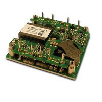
JNC350R41-TZ Lineage Power, JNC350R41-TZ Datasheet

JNC350R41-TZ
Specifications of JNC350R41-TZ
Related parts for JNC350R41-TZ
JNC350R41-TZ Summary of contents
Page 1
Data Sheet August 9, 2010 JNC350R Series Power Modules; DC-DC Converters RoHS Compliant Applications RF Power Amplifier Wireless Networks Switching Networks Options Auto-restart after either output OCP or OVP fault shutdown (“3” option code) Auto-restart ...
Page 2
... Parameter Input Voltage Continuous Transient, operational (≤100 ms) Operating Ambient Temperature Please contact your Lineage Power Sales representative for information on thermal derating when using forced airflow. Operating Case Temperature (See Thermal Considerations section, Figure 20) Storage Temperature ...
Page 3
August 9, 2010 (continued) Electrical Specifications Parameter Output Voltage Set-point ( =25°C) IN IN,nom O O, max c 1 Output Voltage (Over all operating input voltage, resistive load, and temperature conditions until end of ...
Page 4
August 9, 2010 Feature Specifications Unless otherwise indicated, specifications apply over all operating input voltage, resistive load, and temperature conditions. See Feature Descriptions for additional information. Parameter Remote On/Off Signal Interface ( open collector or equivalent, ...
Page 5
Data Sheet August 9, 2010 Characteristic Curves The following figures provide typical characteristics for the JNC350R (28V, 12.5A) at 25ºC. The figures are identical for either positive or negative Remote On/Off logic. 95 Vin=18V 90 Vin=36V 85 Vin=24V 80 75 ...
Page 6
Data Sheet August 9, 2010 Test Configurations Note: Measure the input reflected-ripple current with a simulated source inductance (LTEST µH. Capacitor CS offsets possible battery impedance. Measure the current, as shown above. Figure 7. Input Reflected Ripple Current ...
Page 7
Data Sheet August 9, 2010 Feature Description Remote On/Off Two remote on/off options are available. Positive logic turns the module on during a logic high voltage on the ON/OFF pin, and off during a logic low. Negative logic remote On/Off, ...
Page 8
Data Sheet August 9, 2010 Feature Description (continued) Figure 11. Effective Circuit Configuration for Single-Module Remote-Sense Operation Output Voltage. Output Voltage Programming Trimming allows the user to increase or decrease the output voltage set point of a module. The trim ...
Page 9
Data Sheet August 9, 2010 Feature Description (continued) Examples: To trim down the output of a nominal 28V module to 16.8V % 100 28 V ∆ ...
Page 10
... R will be dependent on the voltage step and range of G the DAC and the desired values for trim-up and trim- down Please contact your Lineage Power Δ%. technical representative to obtain more details on the selection for this resistor. Figure 17. Circuit Configuration to Actively Adjust the Output Voltage. ...
Page 11
... The thermal derating presented in Figure 20 has the JNC350R module thermally coupled to a cold plate inside a sealed clamshell chassis, without any internal air circulation. Please contact your Lineage Power sales representative for information regarding applications where the module is cooled by heat removal into a forced airflow that passes through the interior of the module and over the top baseplate and/or attached heatsink ...
Page 12
... For guidance on appropriate soldering, cleaning and drying procedures, refer to Lineage Power Board Mounted Power Modules: Soldering and Cleaning Application Note. LINEAGE POWER JNC350R Power Modules ...
Page 13
Data Sheet August 9, 2010 EMC Considerations The filter circuit schematic and plots in Figure 21 shows a suggested configuration as tested to meet the conducted emission limits of EN55022 Class B. Note: Customer is ultimately responsible for the proper ...
Page 14
Data Sheet August 9, 2010 Mechanical Outline for Through-Hole Module Dimensions are in inches and [millimeters]. Tolerances: x.xx in. 0.02 in. [x.x mm 0.5 mm] (Unless otherwise indicated) x.xxx in 0.010 in. [x.xx mm 0.25 mm] ...
Page 15
Data Sheet August 9, 2010 Recommended Pad Layout for Through Hole Module Dimensions are in inches and [millimeters]. Tolerances: x.xx in. 0.02 in. [x.x mm 0.5 mm] (Unless otherwise indicated) x.xxx in 0.010 in. [x.xx mm ...
Page 16
... Connector Efficiency Product codes Type 91% Through hole JNC350R41Z 91% Through hole JNC350R641-18Z 91% Through hole JNC350R41-TZ Asia-Pacific Headquarters Tel: +65 6593 7211 Europe, Middle-East and Africa Headquarters Tel: +49 89 878067-280 India Headquarters Tel: +91 80 28411633 Comcodes CC109154927 CC109161262 CC109158457 Document No: DS10-002 ver 1.01 PDF name: JNC350R.pdf ...


