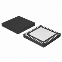
NCP5393MNR2G ON Semiconductor, NCP5393MNR2G Datasheet - Page 17

NCP5393MNR2G
Manufacturer Part Number
NCP5393MNR2G
Description
IC CTLR 2/3/4PHASE CPU 48-QFN
Manufacturer
ON Semiconductor
Datasheet
1.NCP5393MNR2G.pdf
(23 pages)
Specifications of NCP5393MNR2G
Applications
Multiphase Controller
Current - Supply
25mA
Voltage - Supply
4.75 V ~ 5.25 V
Operating Temperature
0°C ~ 70°C
Mounting Type
Surface Mount
Package / Case
48-TQFN Exposed Pad
Mounting Style
SMD/SMT
Lead Free Status / RoHS Status
Lead free / RoHS Compliant
Available stocks
Company
Part Number
Manufacturer
Quantity
Price
Company:
Part Number:
NCP5393MNR2G
Manufacturer:
RFMD
Quantity:
10 000
Part Number:
NCP5393MNR2G
Manufacturer:
ON
Quantity:
20 000
Hardware Jumper Override - V_FIX
controller enters V_FIX mode.The voltage regulator can be
powered when an external SVI bus master is not present.
When in VFIX mode, all of the voltage regulator's output
voltages will be governed by the information shown in
Table 4, regardless of the state of PWROK. VFIX mode is
for debug only. If VFIX mode is necessary for processor
bring-up, VFIXEN, SVC, and SVD should be connected
with jumpers to either ground or VDDIO through suitable
pull-up resistors. SVC and SVD are considered as static
VID and the output voltage will change according to their
status.
•
•
DC IN
VDDIO
ENABLE
PVIEN/
VID[1]
SVC/
VID[3]
SVD/
VID[2]
VDD and VDDNB
PWRGOOD
PWROK
Table 4. SVI VFIX VID CODES (TWO-BIT PARALLEL)
VFIX is an active low pin and when it is pulled low, the
Start-up sequences are presented below:
Boot VID is captured from SVC and SVD pins on
rising edge of ENABLE.
This capture is INDEPENDENT of any other signal.
SVI/PVI is determined by sampling VID[1] during
rising edge of ENABLE (SVI: VID[1]=0, PVI:
VID[1]=1). Once SVI/PVI is determined, the VID
controller is enabled and increments to the Boot VID at
the Soft Start rate. VFIXEN mode is entered once
VFIXEN is asserted.
SVC
0
0
1
1
Outputs Rise to BOOT
VID at SS Rate
VR Turn-On
Command
SVD
0
1
0
1
BOOT VID MSB
BOOT VID LSB
VID[1] Low at Rise of Enable Selects SVI Operation
CPU Can Begin
Serial Data Xfer
Soft-Start is
Complete
Figure 10. Power-Up Sequence in Serial Mode Operation
V
OUT
1.4
1.2
1.0
0.8
(V)
System Power Fault -
Revert to BOOT VID
Possible PWRGOOD
http://onsemi.com
De-Assertion
NCP5393
17
•
•
PWROK De-Assertion
controller uses the previously stored BOOT VID and
regulates all planes to that level performing an on-the-Fly
transition to that level. PWRGOOD remains asserted in this
process.
Power Saving Indicator (PSI_L) and Phase Shedding
controller to indicate when the processor is in a low power
state. NCP5393 uses the PSI_L pin to maximize efficiency
at light loads. When PSI_L = 0, the PSI_L function will be
enabled, and VR system will run in single phase mode. In
power saving mode, NCP5393 works with the NCP5359
driver to represent diode emulation mode at light load for
further power saving. Generally, the PWM outputs are either
high (high side FETs on, low side FET off) or low (high side
FETs off, low FETs on). In NCP5393 only one phase is
enabled in diode emulation mode when Power saving mode
is enabled.
Anytime PWROK de-asserts while EN is asserted, the
The processor provides an output signal to the VR
If VFIXEN is asserted prior to the VID controller
reaching the Boot VID, the VID controller will move to
the VFIXEN VID. Once the first VID value is reached
(either BOOT VID or VFIXEN VID), the VID will
now increment at the Normal rate. Once the VID
controller is enabled, the VID controller can receive
VFIXEN VIDs, independent of PWROK which is
ignored in VFIXEN mode.
If VFIXEN is de-asserted, the device PORs. This
occurs independent of ENABLE
VID Transactions
Resume Serial
VR Turn-Off
PWRGOOD De-Assertion
Command
Causes System PWROK
De-Assertion
Command Forces
PWRGOOD Low
VR Turn-Off


