CP2112EK Silicon Laboratories Inc, CP2112EK Datasheet - Page 12
CP2112EK
Manufacturer Part Number
CP2112EK
Description
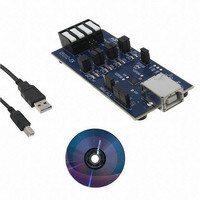
KIT EVAL FOR CP2112
Manufacturer
Silicon Laboratories Inc
Specifications of CP2112EK
Main Purpose
Interface, USB 2.0 to SMBus Bridge
Embedded
No
Utilized Ic / Part
CP2112
Primary Attributes
Full Speed (12Mbps)
Secondary Attributes
LED Status Indicators
Interface Type
USB
Operating Supply Voltage
3.3 V
Product
Interface Development Tools
For Use With/related Products
CP2112
Lead Free Status / RoHS Status
Lead free / RoHS Compliant
Lead Free Status / RoHS Status
Lead free / RoHS Compliant
Other names
336-2010
Available stocks
Company
Part Number
Manufacturer
Quantity
Price
Company:

Part Number:
CP2112EK
Manufacturer:
Silicon Labs
Quantity:
135


CP2112
5. USB Function Controller and Transceiver
The Universal Serial Bus (USB) function controller in the CP2112 is a USB 2.0 compliant full-speed device with
integrated transceiver and on-chip matching and pullup resistors. The USB function controller manages all data
transfers between the USB and the SMBus interface as well as command requests generated by the USB host
controller and commands for controlling the function of the SMBus interface and GPIO pins.
The USB Suspend and Resume modes are supported for power management of both the CP2112 device and
external circuitry. The CP2112 enters Suspend mode when Suspend signaling is detected on the bus. Upon
entering Suspend mode, the Suspend signals are asserted. The Suspend signals are also asserted after a CP2112
reset until device configuration during USB enumeration is complete. SUSPEND is logic high when the device is in
the Suspend state and logic low when the device is in normal mode. The SUSPEND pin has the opposite logic
value of the SUSPEND pin.
The CP2112 exits Suspend mode when any of the following events occur: Resume signaling is detected or
generated, a USB Reset signal is detected, or a device reset occurs. SUSPEND and SUSPEND are weakly pulled
to VIO in a high-impedance state during a CP2112 reset. If this behavior is undesirable, a strong pulldown resistor
(10 k) can be used to ensure SUSPEND remains low during reset. The eight GPIO pins will retain their state
during Suspend mode.
6. System Management Bus (SMBus) Interface
The SMBus I/O interface is a two-wire, bidirectional serial bus. The SMBus is compliant with the System
Management Bus Specification, Version 1.1, and compatible with the I
interface by the system controller are byte-oriented with the SMBus interface autonomously controlling the serial
transfer of the data. The CP2112 operates as an SMBus master; however, it has an SMBus slave address that is
configurable. The CP2112 will only ACK this address and will not respond to any read or write requests. If the least
significant bit of the address is set, the device will ignore it.
6.1. SMBus Configuration
Figure 5 shows a typical SMBus configuration. The SMBus specification allows any recessive voltage between
3.0 V and 5.0 V; different devices on the bus may operate at different voltage levels. The bidirectional serial clock
(SCL) and serial data (SDA) lines must be connected to a positive power supply voltage through a pullup resistor or
similar circuit. Every device connected to the bus must have an open-drain or open-collector output for both the
SCL and SDA lines so that both are pulled high (recessive state) when the bus is free. The maximum number of
devices on the bus is limited only by the requirement that the rise and fall times on the bus not exceed 300 ns and
1000 ns, respectively. The SMBus provides control of SDA, SCL generation and synchronization, arbitration logic,
and START/STOP control and generation.
12
VDD = 5 V
(Master Device)
Figure 5. Typical SMBus Configuration
VDD = 3 V
CP2112
Rev. 1.0
VDD = 5 V
Device 1
Slave
2
C serial bus. Reads and writes to the
VDD = 3 V
Device 2
Slave
SDA
SCL
Related parts for CP2112EK
Image
Part Number
Description
Manufacturer
Datasheet
Request
R

Part Number:
Description:
QFN 24/-40 TO 85 OC/HID USB TO SMBUS BRIDGE
Manufacturer:
Silicon Laboratories Inc
Datasheet:

Part Number:
Description:
IC HID USB-TO-SMBUS BRIDGE 24QFN
Manufacturer:
Silicon Laboratories Inc
Datasheet:
Part Number:
Description:
SMD/C°/SINGLE-ENDED OUTPUT SILICON OSCILLATOR
Manufacturer:
Silicon Laboratories Inc
Part Number:
Description:
Manufacturer:
Silicon Laboratories Inc
Datasheet:
Part Number:
Description:
N/A N/A/SI4010 AES KEYFOB DEMO WITH LCD RX
Manufacturer:
Silicon Laboratories Inc
Datasheet:
Part Number:
Description:
N/A N/A/SI4010 SIMPLIFIED KEY FOB DEMO WITH LED RX
Manufacturer:
Silicon Laboratories Inc
Datasheet:
Part Number:
Description:
N/A/-40 TO 85 OC/EZLINK MODULE; F930/4432 HIGH BAND (REV E/B1)
Manufacturer:
Silicon Laboratories Inc
Part Number:
Description:
EZLink Module; F930/4432 Low Band (rev e/B1)
Manufacturer:
Silicon Laboratories Inc
Part Number:
Description:
I°/4460 10 DBM RADIO TEST CARD 434 MHZ
Manufacturer:
Silicon Laboratories Inc
Part Number:
Description:
I°/4461 14 DBM RADIO TEST CARD 868 MHZ
Manufacturer:
Silicon Laboratories Inc
Part Number:
Description:
I°/4463 20 DBM RFSWITCH RADIO TEST CARD 460 MHZ
Manufacturer:
Silicon Laboratories Inc
Part Number:
Description:
I°/4463 20 DBM RADIO TEST CARD 868 MHZ
Manufacturer:
Silicon Laboratories Inc
Part Number:
Description:
I°/4463 27 DBM RADIO TEST CARD 868 MHZ
Manufacturer:
Silicon Laboratories Inc
Part Number:
Description:
I°/4463 SKYWORKS 30 DBM RADIO TEST CARD 915 MHZ
Manufacturer:
Silicon Laboratories Inc