RF1211 RFM, RF1211 Datasheet
RF1211
Manufacturer Part Number
RF1211
Description
Filters 315.00MHz Narrowband Receiver Front End
Manufacturer
RFM
Type
SAW Filtersr
Datasheet
1.RF1211.pdf
(2 pages)
Specifications of RF1211
Product
RF SAW Filters
Frequency
315 MHz
Frequency Range
314.92 MHz to 315.8 MHz
Package / Case
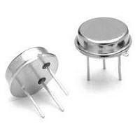
TO-39-3
Operating Temperature Range
- 40 C to + 85 C
Voltage Rating
30 V
Termination Style
Radial
Lead Free Status / RoHS Status
Lead free / RoHS Compliant
Available stocks
Company
Part Number
Manufacturer
Quantity
Price
Company:

Part Number:
RF1211
Manufacturer:
RFMD
Quantity:
5 000
Company:
Part Number:
RF1211B
Manufacturer:
NXP
Quantity:
5 584
Company:
Part Number:
RF1211C
Manufacturer:
RFMD
Quantity:
5 000
Company:
Part Number:
RF1211D
Manufacturer:
RFMD
Quantity:
5 000


Electrical Characteristics
www.RFM.com
©2008 by RF Monolithics, Inc.
Notes:
1.
2.
3.
4.
5.
6.
7.
8.
• Ideal Front-End Filter for USA Automotive Wireless Receivers
• Low-Loss, Coupled-Resonator Quartz Design
• Simple External Impedance Matching
• Rugged TO39 Hermetic Package
• Complies with Directive 2002/95/EC (RoHS)
The RF1211 is a low-loss, compact, and economical surface-acoustic-wave (SAW) filter designed
to provide front-end selectivity in 315.0 MHz receivers. Receiver designs using this filter include
superhet with 10.7 MHz or 500 kHz IF, direct conversion and superregen. Typical applications of
these receivers are wireless remote-control and security devices (especially for automotive
keyless entry) operating in the USA under FCC Part 15, in Canada under DOC RSS-210, and in
Italy.
This coupled-resonator filter (CRF) uses selective null placement to provide suppression, typically
greater than 40 dB, of the LO and image spurious responses of superhet receivers with 10.7 MHz
IF. RFM’s advanced SAW design and fabrication technology is utilized to achieve high
performance and very low loss with simple external impedance matching (not included). Quartz
construction provides excellent frequency stability over a wide temperature range.
Characteristic
Center Frequency at 25°C
Insertion Loss
3 dB Bandwidth
Rejection
Temperature
Frequency Aging
External Impedance
Lid Symbolization (in addition to Lot and/or Date Codes)
Unless noted otherwise, all measurements are made with the filter installed in the specified test fixture which is connected to a 50
VSWR
and passband shape are dependent on the impedance matching component values and quality.
The frequency f
Unless noted otherwise, specifications apply over the entire specified operating temperature range.
The turnover temperature, T
be calculated from: f = f
Frequency aging is the change in fc with time and is specified at +65°C or less. Aging may exceed the specification for prolonged temperatures
above +65°C. Typically, aging is greatest the first year after manufacture, decreasing significantly in subsequent years.
The design, manufacturing process, and specifications of this device are subject to change without notice.
One or more of the following U.S. Patents apply: 4,54,488, 4,616,197, and others pending.
All equipment designs utilizing this product must be approved by the appropriate government agency prior to manufacture or sale.
CAUTION: Electrostatic Sensitive Device. Observe precautions for handling.
1.2:1. The test fixture L and C are adjusted for minimum insertion loss at the filter center frequency, f
E-mail: info@rfm.com
c
is defined as the midpoint between the 3dB frequencies.
o
[1 - FTC (T
Absolute Frequency
Tolerance from 315.0 MHz
at f
at f
Ultimate
Operating Case Temp.
Turnover Temperature
Turnover Frequency
Freq. Temp. Coefficient
Series Inductance
Shunt Capacitance
Absolute Value during the First Year
O
c
c
, is the temperature of maximum (or turnover) frequency, f
- 21.4 MHz (Image)
- 10.7 MHz (LO)
o
- T
c
)
2
].
Pb
Sym
BW
FTC
|fA|
T
T
IL
f
f
C
L
O
c
fc
C
O
3
Notes
1, 2
1, 2
3, 4
1
1
5
1
o
. The nominal frequency at any case temperature, T
Minimum
314.92
500
-40
40
15
22
RFM RF1211
86 nH (Pin 1), 82 nH (Pin 2)
Typical
315.00
0.032
700
1.7
50
40
37
80
f
10
c
9
c
. Note that insertion loss, bandwidth,
SAW Filter
315.0 MHz
RF1211
TO39-3 Case
Maximum
315.080
±80
800
+85
3.0
52
test system with
RF1211 - 3/21/08
ppm/°C
ppm/yr
Page 1 of 2
Units
MHz
MHz
kHz
dB
dB
dB
pF
°C
°C
c
, may
2
Related parts for RF1211
Image
Part Number
Description
Manufacturer
Datasheet
Request
R

Part Number:
Description:
Filters 1575.42 MHz, GPS RF SAW Filter
Manufacturer:
RFM
Datasheet:

Part Number:
Description:
Filters 915MHz, ISM Band RF SAW Filter
Manufacturer:
RFM
Datasheet:
Part Number:
Description:
Filters 1960MHz, PCS RF SAW Filter
Manufacturer:
RFM
Datasheet:

Part Number:
Description:
Filters 149.0MHz, Orbcom TX RF SAW Filter
Manufacturer:
RFM
Datasheet:

Part Number:
Description:
Filters 433.92MHz, ISM Band RF SAW Filter
Manufacturer:
RFM
Datasheet:
Part Number:
Description:
Filters 1842.5MHz, DCS RF SAW Filter
Manufacturer:
RFM
Datasheet:

Part Number:
Description:
Filters 810 MHz RF SAW Filter
Manufacturer:
RFM
Datasheet:
Part Number:
Description:
Filters 915MHz, ISM Band RF SAW Filter
Manufacturer:
RFM
Datasheet:

Part Number:
Description:
Filters 137.5MHz, Orbcom RX RF SAW Filter
Manufacturer:
RFM
Datasheet:
Part Number:
Description:
Filters 942.5MHz, EGSM RF SAW Filter
Manufacturer:
RFM
Datasheet:


Part Number:
Description:
10-Terminal Ceramic Surface-Mount Case 7 x 5 mm Nominal Footprint
Manufacturer:
RFM [RF Monolithics, Inc]
Datasheet:
Part Number:
Description:
QUAD-BAND GSM850/GSM/DCS/PCS POWER AMP MODULE
Manufacturer:
RFM [RF Monolithics, Inc]
Datasheet:
Part Number:
Description:
402 to 405 MHz Medical Band Front-end Filter
Manufacturer:
RFM [RF Monolithics, Inc]
Datasheet:
Part Number:
Description:
674.03 MHz SAW Resonator
Manufacturer:
RFM [RF Monolithics, Inc]
Datasheet:
RF1211 Summary of contents
Page 1
... Rugged TO39 Hermetic Package • Complies with Directive 2002/95/EC (RoHS) The RF1211 is a low-loss, compact, and economical surface-acoustic-wave (SAW) filter designed to provide front-end selectivity in 315.0 MHz receivers. Receiver designs using this filter include superhet with 10.7 MHz or 500 kHz IF, direct conversion and superregen. Typical applications of ...
Page 2
... D (3 places places) Millimeters Min Max A 9.40 B 3.18 C 2.50 3.50 D 0.46 Nominal E 5.08 Nominal F 2.54 Nominal G 2.54 Nominal H 1. 45° Inches Min Max 0.370 0.125 0.098 0.138 0.018 Nominal 0.200 Nominal 0.100 Nominal 0.100 Nominal 0.040 0.055 Page RF1211 - 3/21/08 ...