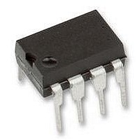
THAT1646P08-U THAT Corporation, THAT1646P08-U Datasheet - Page 5

THAT1646P08-U
Manufacturer Part Number
THAT1646P08-U
Description
IC, BALANCED LINE DRIVER, DIP-8
Manufacturer
THAT Corporation
Datasheet
1.THAT1646P08-U.pdf
(12 pages)
Specifications of THAT1646P08-U
Device Type
Differential Line
Supply Voltage Range
± 4V To ± 18V
Driver Case Style
DIP
No. Of Pins
8
Operating Temperature Range
-40°C To +85°C
Termination Type
Through Hole
Filter Terminals
Through Hole
Rohs Compliant
Yes
No. Of Amplifiers
1
Lead Free Status / RoHS Status
Lead free / RoHS Compliant
THAT1606/1646 Balanced Line Driver ICs
OutSmarts
OutSmarts topology, a variation of circuitry originally
developed by Chris Strahm at Audio Teknology Inc.,
(and later acquired by Audio Toys, Inc.).
OutSmarts topology employs two negative-feedback
loops -- one to control the differential signal, and a
separate loop to control the common mode output
levels.
the 1606 and 1646. The gain core is a single ampli-
fier that includes two differential input pairs, Cin+/-
and Din+/-, and complementary outputs, Vout+ and
Vout-, related to each other by two gain expressions,
A
Din+/-, is connected to the differential feedback net-
work between the outputs and the input signal. The
second differential input pair, Cin+/-, is connected to
a bridge circuit which generates an error signal used
to servo the common-mode behavior of the outputs.
The loop equations are then:
where AD is the differential open-loop gain, and
where AC is the common-mode open-loop gain.
dard op-amp loop equations.
can see that this results in:
that defines differential operation yields:
Dividing through by A
simplifying yields
as one would expect for a +6 dB line driver.
4. The 10 pF capacitor can be ignored for the purposes of this analysis. It simply limits the maximum frequency at which the current-sensing action occurs
D
(s) and A
The THAT 1606 and 1646 family employs the
Figures 2 and 3 show the gain core common to
D
D
These equations can be solved much like stan-
For the differential case, using superposition, we
D
D
Substituting and simplifying into the equation
D
D D
OUT
OUT
IN
IN
D
+
-
OUT
OUT
+
+
=
=
-
+
1
1
=
=
C
3
3
D
D
(s). The first pair of differential inputs,
[
D
D
2
OUT
®
OUT
OUT
OUT
A
(
technology
D
In
-
-
+
-
-
+
D
=
=
-
THAT Corporation; 45 Sumner Street; Milford, Massachusetts 01757-1656; USA
+
+
D
3
D
S
In
D
OUT
Tel: +1 (508) 478-9200; Fax: +1 (508) 478-0990; Web: www.thatcorp.com
2
2
3
3
-
D
(assuming that A
D
)
In
In
OUT
OUT
+
.
+
-
3
2
.
, and
(
=
In
=
Copyright © 2007, THAT Corporation; All rights reserved.
A
+
A
D
C
-
(
(
In
D
C
IN
-
IN
) .
]
+
+
D
Theory of Operation
-
-
D
>> 3) and
C
IN
IN
THAT's
-
-
)
)
,
,
Page 5 of 12
the differential equation above simplifies to:
in that it is dependent on the attached load, and in
any event doesn't yield much insight into the device's
operation.
complete discussion is given in the reference men-
tioned in note 1.
the combination of negative feedback and high
open-loop gain usually results in the open-loop gain
"dropping out" of the equation, and the differential in-
puts being forced to the same potential. This is true
for the core of the 1606 and 1646 ICs. If we start
with that assumption, the operation of the com-
mon-mode feedback loop can be intuited as follows:
mode input actually senses the sum of each IC's out-
put currents by way of two 25 W resistors and the
bridge network
fied and then summed into both outputs, with the net
effect being to force the sum of the currents to be
zero, and thus the common mode output current to
zero.
pens when the IC is loaded with a single-ended load,
which shorts one or the other output to ground.
Suppose Out- is grounded. In this case, the differen-
tial feedback loop increases the voltage at Dout+ to
make up for most of the signal lost to the short at
Out-. The common-mode feedback loop forces the
current from Out- to be equal and opposite to that
from Out+. But, during peak signals which drive
Dout+ into clipping (exceeding its maximum output
voltage capability), the differential loop is starved for
feedback. Without the common-mode feedback, the
result would be for the voltage at Dout- to decrease in
an attempt to satisfy the differential loop's demand
for feedback.
conventional cross-coupled output designs – com-
mon-mode feedback is lost when one output is
clipped while the other is grounded.
feedback loop senses this happening because of the
increase in current at Out- (compared to that at
Out+), and prevents the voltage at Out- from rising
For the 1646, In- is hard-wired to ground (0v), so
D D
The common mode equation is more complicated
In op-amp analysis using negative feedback loops,
Referring again to Figures 2 and 3, the common-
To see why this is important, consider what hap-
With OutSmarts, however, the common mode
OUT
=
For those who are interested, a more
2
(
4
This is one significant weakness of
In
. The resulting error signal is ampli-
+
)
.
Document 600078 Rev 04


