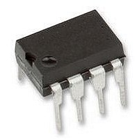
THAT1646P08-U THAT Corporation, THAT1646P08-U Datasheet - Page 8

THAT1646P08-U
Manufacturer Part Number
THAT1646P08-U
Description
IC, BALANCED LINE DRIVER, DIP-8
Manufacturer
THAT Corporation
Datasheet
1.THAT1646P08-U.pdf
(12 pages)
Specifications of THAT1646P08-U
Device Type
Differential Line
Supply Voltage Range
± 4V To ± 18V
Driver Case Style
DIP
No. Of Pins
8
Operating Temperature Range
-40°C To +85°C
Termination Type
Through Hole
Filter Terminals
Through Hole
Rohs Compliant
Yes
No. Of Amplifiers
1
Lead Free Status / RoHS Status
Lead free / RoHS Compliant
Document 600078 Rev 04
1606.
spects. First, the 1606 includes a negative-sense in-
put pin (pin 6), so offers a differential input. This
can be useful in connecting the output driver to the
output of modern D/A converters, which usually pres-
ent differential outputs. Second, instead of two 10uF
capacitors, the 1606 uses an 0.1uf capacitor (C1)
and 1MW (R1) resistor to reduce common-mode dc
offset. Generally, these components will cost less, and
take up less space on the circuit board than the two
1606 circuits
Figure 6 shows the most basic connection for a
Figure 6. Basic THAT 1606 application circuit with output common mode offset reduction and single-ended input drive
The 1606 differs from the 1646 in two re-
Figure 7. Basic THAT 1606 application circuit with output common mode offset reduction and differential drive
THAT Corporation; 45 Sumner Street; Milford, Massachusetts 01757-1656; USA
Tel: +1 (508) 478-9200; Fax: +1 (508) 478-0990; Web: www.thatcorp.com
In+
In-
In
100n
100n
100n
100n
Copyright © 2007, THAT Corporation; All rights reserved.
C4
C4
C5
C5
7
6
5
7
6
5
Gnd
Gnd
In+
In-
In+
In-
12
12
11
11
Vcc
Vee
Vcc
Vee
Vee
Vee
Vcc
Vcc
Cap1
13
Cap1
13
Cap2
Cap2
Page 8 of 12
Out+
Out-
U1
THAT1606
Out+
Out-
U1
THAT1606
100n
100n
C1
C1
14
3
14
3
large capacitors required for the 1646. C1 should be
a high-quality film type capacitor to minimize low-fre-
quency distortion when driving single-ended loads.
dreds of feet in length without becoming unstable,
but such long cables can act as antennae which can
pick up RFI and direct it into the circuit. The circuit
of Figure 8 includes two 100 pF bypass capacitors C3
and C8 and two ferrite beads, whose purpose is to
redirect this RF energy to the chassis before it can
circulate inside the product's box and couple RF into
RFI protection
These line drivers can easily drive cables hun-
1M0
1M0
R1
R1
THAT1606/1646 Balanced Line Driver ICs
XLR (M)
XLR (M)
1
1
3
3
2
2


