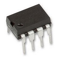
THAT1646P08-U THAT Corporation, THAT1646P08-U Datasheet - Page 6

THAT1646P08-U
Manufacturer Part Number
THAT1646P08-U
Description
IC, BALANCED LINE DRIVER, DIP-8
Manufacturer
THAT Corporation
Datasheet
1.THAT1646P08-U.pdf
(12 pages)
Specifications of THAT1646P08-U
Device Type
Differential Line
Supply Voltage Range
± 4V To ± 18V
Driver Case Style
DIP
No. Of Pins
8
Operating Temperature Range
-40°C To +85°C
Termination Type
Through Hole
Filter Terminals
Through Hole
Rohs Compliant
Yes
No. Of Amplifiers
1
Lead Free Status / RoHS Status
Lead free / RoHS Compliant
Document 600078 Rev 04
out of control. This causes the OutSmarts design to
more closely mimic the behavior of a true floating
are relatively straightforward. A quiet, solid ground
reference, stiff voltage supplies, and adequate supply
bypassing are all that are required to achieve excel-
lent performance out of both ICs. Both devices must
be driven from a low-impedance source, preferably
directly from opamp outputs, to maintain the
specified performance.
and the maximum capacitance is limited only by slew
rate and frequency response considerations.
lation, the line driver's 25W sense resistors can be
lumped into a single 50W resistor. The correct cable
capacitance to use for the balanced-signal case is the
sum of the inter-conductor capacitance and the two
conductor-to-shield capacitances in series.
manufacturers only specify the inter-conductor ca-
pacitance and the capacitance of one conductor to
the other while connected to the shield, and some ex-
traction may be required.
ing with 34 pF/ft of inter-conductor capacitance and
67 pF/ft of conductor to "other conductor + shield
5. Dennis A. Bohn, “Practical Line-Driving Current Requirements“(Rane Note 126), Rane Corporation, 1991, revised 5/1996. Available at www.rane.com/note126.html.
Stability and Load Capacitance
Circuit implementations using the 1606 and 1646
The devices are stable into any capacitive load,
For the purposes of the frequency response calcu-
As an example, Belden 8451 is specified as hav-
THAT Corporation; 45 Sumner Street; Milford, Massachusetts 01757-1656; USA
Tel: +1 (508) 478-9200; Fax: +1 (508) 478-0990; Web: www.thatcorp.com
In
100n
100n
C4
Copyright © 2007, THAT Corporation; All rights reserved.
C5
4
3
Figure 4. Basic THAT 1646 application circuit
In
Gnd
Vcc
Vee
Vee
Vcc
Sns+
Applications
Sns-
Some
Page 6 of 12
Out+
Out-
U1
THAT1646
8
1
balanced source (such as a transformer), compared
to the behavior of a conventional CCOS design.
capacitance". Thus, we can assume a single conduc-
tor-to-shield capacitance of 33 pF/ft (the difference
between 67 and 34) for each conductor. For balanced
signals, the load capacitance across the 1646 outputs
will be 34 pF/ft + 16.5 pF/ft = 50.5 pF/ft. The corner
frequency of the THAT 1646 driving 500 ft of this ca-
ble (25.25 nF) will be 126 kHz.
posed by excessive cable and other capacitances. We
know that
and that
work specifying some of the requirements for a bal-
anced line driver, including a) stability into reactive
loads, b) differential output voltage swing of at least
±11 volts peak (+20dBu), and c) reliability
work suggests a reasonable rule by which to calculate
the output current requirements at 20kHz. The au-
thor concludes that the actual worst case peak level
i
One must also consider the slew rate limitations
Dennis Bohn of Rane Corporation has published
dV
dt
f
C
=
C
=
=
V
dV
2
dt
Peak
×
p
×
THAT1606/1646 Balanced Line Driver ICs
50
2 p
XLR (M)
W
1
×
×
500 34
3
×
f
(
1
2
pF
ft
+
16 5
.
pF
ft
)
=
126
kHz
5
. This


