PIC16LF1827-I/MV Microchip Technology, PIC16LF1827-I/MV Datasheet - Page 256
PIC16LF1827-I/MV
Manufacturer Part Number
PIC16LF1827-I/MV
Description
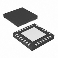
IC, 8BIT MCU, PIC16LF, 32MHZ, QFN-28
Manufacturer
Microchip Technology
Series
PIC® XLP™ 16Fr
Specifications of PIC16LF1827-I/MV
Controller Family/series
PIC16LF
Eeprom Memory Size
256Byte
Ram Memory Size
384Byte
Cpu Speed
32MHz
No. Of Timers
5
Interface
EUSART, I2C, SPI
Core Size
8 Bit
Program Memory Size
4kWords
Core Processor
PIC
Speed
32MHz
Connectivity
I²C, SPI, UART/USART
Peripherals
Brown-out Detect/Reset, POR, PWM, WDT
Number Of I /o
16
Program Memory Type
FLASH
Eeprom Size
256 x 8
Ram Size
384 x 8
Voltage - Supply (vcc/vdd)
1.8 V ~ 3.6 V
Data Converters
A/D 12x10b
Oscillator Type
Internal
Operating Temperature
-40°C ~ 85°C
Package / Case
28-UFQFN Exposed Pad
Processor Series
PIC16LF
Core
PIC
Data Ram Size
256 B
Maximum Clock Frequency
32 KHz
Number Of Programmable I/os
16
Number Of Timers
5
Operating Supply Voltage
1.8 V to 3.6 V
Maximum Operating Temperature
+ 125 C
3rd Party Development Tools
52715-96, 52716-328, 52717-734
Development Tools By Supplier
PG164130, DV164035, DV244005, DV164005
Minimum Operating Temperature
- 40 C
On-chip Adc
10 bit, 12 Channel
On-chip Dac
5 bit
Lead Free Status / RoHS Status
Lead free / RoHS Compliant
Lead Free Status / RoHS Status
Lead free / RoHS Compliant
Available stocks
Company
Part Number
Manufacturer
Quantity
Price


PIC16F/LF1826/27
24.5.3.3
Setting the AHEN bit of the SSPxCON3 register
enables additional clock stretching and interrupt gen-
eration after the 8th falling edge of a received match-
ing address. Once a matching address has been
clocked in, CKP is cleared and the SSPxIF interrupt is
set.
Figure 24-18 displays a standard waveform of a 7-bit
Address Slave Transmission with AHEN enabled.
1.
2.
3.
4.
5.
6.
7.
8.
9.
10. Slave hardware automatically clears the CKP bit
11. Slave software clears SSPxIF.
12. Slave loads value to transmit to the master into
13. Slave sets CKP bit releasing the clock.
14. Master clocks out the data from the slave and
15. Slave hardware copies the ACK value into the
16. Steps 10-15 are repeated for each byte transmit-
17. If the master sends a not ACK the slave
DS41391C-page 256
Note: SSPxBUF cannot be loaded until after the
Note: Master must send a not ACK on the last byte
Bus starts Idle.
Master sends Start condition; the S bit of SSPx-
STAT is set; SSPxIF is set if interrupt on Start
detect is enabled.
Master sends matching address with R/W bit
set. After the 8th falling edge of the SCLx line the
CKP bit is cleared and SSPxIF interrupt is gen-
erated.
Slave software clears SSPxIF.
Slave software reads ACKTIM bit of SSPxCON3
register, and R/W and D/A of the SSPxSTAT
register to determine the source of the interrupt.
Slave reads the address value from the SSPx-
BUF register clearing the BF bit.
Slave software decides from this information if it
wishes to ACK or not ACK and sets ACKDT bit
of the SSPxCON2 register accordingly.
Slave sets the CKP bit releasing SCLx.
Master clocks in the ACK value from the slave.
and sets SSPxIF after the ACK if the R/W bit is
set.
SSPxBUF setting the BF bit.
sends an ACK value on the 9th SCLx pulse.
ACKSTAT bit of the SSPxCON2 register.
ted to the master from the slave.
releases the bus allowing the master to send a
Stop and end the communication.
ACK.
to ensure that the slave releases the SCLx
line to receive a Stop.
7-bit Transmission with Address
Hold Enabled
Preliminary
2010 Microchip Technology Inc.
Related parts for PIC16LF1827-I/MV
Image
Part Number
Description
Manufacturer
Datasheet
Request
R

Part Number:
Description:
IC, 8BIT MCU, PIC16LF, 32MHZ, QFN-28
Manufacturer:
Microchip Technology
Datasheet:

Part Number:
Description:
IC, 8BIT MCU, PIC16LF, 32MHZ, DIP-18
Manufacturer:
Microchip Technology
Datasheet:

Part Number:
Description:
IC, 8BIT MCU, PIC16LF, 20MHZ, TQFP-44
Manufacturer:
Microchip Technology
Datasheet:
Part Number:
Description:
7 KB Flash, 384 Bytes RAM, 32 MHz Int. Osc, 16 I/0, Enhanced Mid Range Core, Nan
Manufacturer:
Microchip Technology

Part Number:
Description:
14KB Flash, 512B RAM, LCD, 11x10b ADC, EUSART, NanoWatt XLP 28 SOIC .300in T/R
Manufacturer:
Microchip Technology
Datasheet:
Part Number:
Description:
14KB Flash, 512B RAM, LCD, 11x10b ADC, EUSART, NanoWatt XLP 28 SSOP .209in T/R
Manufacturer:
Microchip Technology
Datasheet:
Part Number:
Description:
MCU PIC 14KB FLASH XLP 28-SSOP
Manufacturer:
Microchip Technology
Part Number:
Description:
MCU PIC 14KB FLASH XLP 28-SOIC
Manufacturer:
Microchip Technology
Part Number:
Description:
MCU PIC 512B FLASH XLP 28-UQFN
Manufacturer:
Microchip Technology
Part Number:
Description:
MCU PIC 14KB FLASH XLP 28-SPDIP
Manufacturer:
Microchip Technology

Part Number:
Description:
MCU 7KB FLASH 256B RAM 40-UQFN
Manufacturer:
Microchip Technology
Part Number:
Description:
MCU 7KB FLASH 256B RAM 44-TQFP
Manufacturer:
Microchip Technology

Part Number:
Description:
MCU 14KB FLASH 1KB RAM 28-UQFN
Manufacturer:
Microchip Technology
Part Number:
Description:
MCU PIC 14KB FLASH XLP 40-UQFN
Manufacturer:
Microchip Technology
Part Number:
Description:
MCU PIC 14KB FLASH XLP 44-TQFP
Manufacturer:
Microchip Technology