LM2588S-12 National Semiconductor, LM2588S-12 Datasheet - Page 28
LM2588S-12
Manufacturer Part Number
LM2588S-12
Description
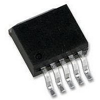
IC, FLYBACK REGULATOR, TO-263-7
Manufacturer
National Semiconductor
Datasheet
1.LM2588S-ADJNOPB.pdf
(30 pages)
Specifications of LM2588S-12
Primary Input Voltage
5V
No. Of Outputs
1
Output Voltage
12V
Output Current
5A
No. Of Pins
7
Operating Temperature Range
-40°C To +125°C
Supply Voltage Range
4V To 40V
Termination Type
SMD
Lead Free Status / RoHS Status
Contains lead / RoHS non-compliant
Available stocks
Company
Part Number
Manufacturer
Quantity
Price

Part Number:
LM2588S-12
Manufacturer:
TI/德州仪器
Quantity:
20 000


www.national.com
Application Hints
HEAT SINK/THERMAL CONSIDERATIONS
In many cases, a heat sink is not required to keep the
LM2588 junction temperature within the allowed operating
temperature range. For each application, to determine
whether or not a heat sink will be required, the following must
be identified:
1) Maximum ambient temperature (in the application).
2) Maximum regulator power dissipation (in the application).
3) Maximum allowed junction temperature (125˚C for the
LM2588). For a safe, conservative design, a temperature
approximately 15˚C cooler than the maximum junction tem-
perature should be selected (110˚C).
4) LM2588 package thermal resistances θ
in the Electrical Characteristics).
Total power dissipated (P
as follows:
Boost:
V
N is the transformer turns ratio, D is the duty cycle, and I
is the maximum load current (and
maximum load currents for multiple-output flyback regula-
tors). The duty cycle is given by:
Boost:
where V
typically 0.5V for Schottky diodes and 0.8V for fast recovery
diodes. V
found in the Characteristic Curves.
When no heat sink is used, the junction temperature rise is:
IN
is the minimum input voltage, V
F
SAT
is the forward biased voltage of the diode and is
is the switch saturation voltage and can be
∆T
J
D
) by the LM2588 can be estimated
= P
D
(Continued)
• θ
OUT
∑
JA
I
.
LOAD
is the output voltage,
JA
is the sum of the
and θ
JC
(given
LOAD
28
Adding the junction temperature rise to the maximum ambi-
ent temperature gives the actual operating junction tempera-
ture:
If the operating junction temperature exceeds the maximum
junction temperatue in item 3 above, then a heat sink is
required. When using a heat sink, the junction temperature
rise can be determined by the following:
Again, the operating junction temperature will be:
As before, if the maximum junction temperature is exceeded,
a larger heat sink is required (one that has a lower thermal
resistance).
Included in the Switchers Made Simple design software is a
more precise (non-linear) thermal model that can be used to
determine junction temperature with different input-output
parameters or different component values. It can also calcu-
late the heat sink thermal resistance required to maintain the
regulator junction temperature below the maximum operat-
ing temperature.
To further simplify the flyback regulator design procedure,
National Semiconductor is making available computer de-
sign software Switchers Made Simple. Software is available
on a (3
National Semiconductor sales office in your area or the
National
(1-800-272-9959).
1
⁄
2
") diskette for IBM compatible computers from a
∆T
Semiconductor
J
= P
D
• (θ
T
T
J
JC
J
= ∆T
= ∆T
+ θ
Customer
Interface
J
J
+ T
+ T
A
A
.
+ θ
Response
Heat Sink
)
Center
Related parts for LM2588S-12
Image
Part Number
Description
Manufacturer
Datasheet
Request
R

Part Number:
Description:
IC, FLYBACK REGULATOR, TO-263-7
Manufacturer:
National Semiconductor
Datasheet:

Part Number:
Description:
SIMPLE SWITCHER 5A Flyback Regulator with
Manufacturer:
National Semiconductor
Datasheet:
Part Number:
Description:
IC MULTI CONFIG SYNC 5V TO263-7
Manufacturer:
National Semiconductor
Datasheet:
Part Number:
Description:
IC MULT CONFIG SYNC 3.3V TO263-7
Manufacturer:
National Semiconductor
Datasheet:
Part Number:
Description:
IC REG SIMPLE SWITCHER TO-263-7
Manufacturer:
National Semiconductor
Datasheet:
Part Number:
Description:
IC REG SIMPLE SWITCHER TO-263-7
Manufacturer:
National Semiconductor
Datasheet:
Part Number:
Description:
National Semiconductor [8-Bit D/A Converter]
Manufacturer:
National Semiconductor
Datasheet:
Part Number:
Description:
National Semiconductor [Media Coprocessor]
Manufacturer:
National Semiconductor
Datasheet:
Part Number:
Description:
Digitally Controlled Tone and Volume Circuit with Stereo Audio Power Amplifier, Microphone Preamp Stage and National 3D Sound
Manufacturer:
National Semiconductor
Datasheet:
Part Number:
Description:
Digitally Controlled Tone and Volume Circuit with Stereo Audio Power Amplifier, Microphone Preamp Stage and National 3D Sound
Manufacturer:
National Semiconductor
Datasheet:
Part Number:
Description:
AC97 Rev 2 Codec with Sample Rate Conversion and National 3D Sound
Manufacturer:
National Semiconductor
Part Number:
Description:
Manufacturer:
National Semiconductor
Datasheet:
Part Number:
Description:
Manufacturer:
National Semiconductor
Datasheet: