AS5134-ASSU austriamicrosystems, AS5134-ASSU Datasheet - Page 15

AS5134-ASSU
Manufacturer Part Number
AS5134-ASSU
Description
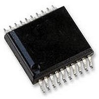
ENCODER, MAGNETIC, ROTARY, 8BIT, 20SSOP
Manufacturer
austriamicrosystems
Datasheet
1.AS5134-ASSU.pdf
(39 pages)
Specifications of AS5134-ASSU
Brief Features
9-Bit Multiturn Counter, User Programmable Zero Position And Sensitivity
Supply Voltage Range
4.5V To 5.5V
Operating Temperature Range
-40°C To +140°C
Digital Ic Case
RoHS Compliant
Ic Function
Programmable High Speed Magnetic Rotary Encoder
Rohs Compliant
Yes
AS5134
Data Sheet - D e t a i l e d D e s c r i p t i o n
Quadrature A/B/Index Output
The phase shift between channel A and B indicates the direction of the magnet movement. Channel A leads channel B
at a clockwise rotation of the magnet (top view) by 90 electrical degrees. Channel B leads channel A at a counter-
clockwise rotation.
Figure 10. Incremental Output Modes
Table 7. Programming Options for the Quadrature Signals A/B/Index
Brushless DC Motor Commutation Mode
The BLDC signals will be used to control the electrical angle information – according to the amount of pole pairs and
the actual mechanical angle position. Refer
Serial Synchronous Interface (SSI) on page
Figure 11. Commutation Mode
www.austriamicrosystems.com
α
W
0
0
1
1
U
V
electrical
Quad A/B/Index-Mode
Abi (13:12)
pole pair : 2
0
0
:= α
Index
A
B
mechanical
60
30
0
1
0
1
*n
120
60
pole_pairs
180
90
Figure
19.
240
120
for an example of n_pole_pairs:=2. For the programming, refer to
A → pin A, B → pin B, I(index) → pin I default value)
pulse → pin A, direction → pin B, I(index) → pin I
Revision 1.8
step → pin A, direction → pin B, I(index) → pin I
Zero Position
Function: output multiplexer for pin A,B,I
Mechanical
off: LO → pin A, LO → pin B, LO → pin I
300
150
Index=0
3 LSB
1 LSB
max.
180
0
Rotation Direction
Change
210
60
Hyst=
2LSB
Zero Position
Mechanical
120
240
180
270
angle electrical
angle mechanical
15 - 39


