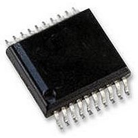
AS5134-ASSU austriamicrosystems, AS5134-ASSU Datasheet - Page 32

AS5134-ASSU
Manufacturer Part Number
AS5134-ASSU
Description
ENCODER, MAGNETIC, ROTARY, 8BIT, 20SSOP
Manufacturer
austriamicrosystems
Datasheet
1.AS5134-ASSU.pdf
(39 pages)
Specifications of AS5134-ASSU
Brief Features
9-Bit Multiturn Counter, User Programmable Zero Position And Sensitivity
Supply Voltage Range
4.5V To 5.5V
Operating Temperature Range
-40°C To +140°C
Digital Ic Case
RoHS Compliant
Ic Function
Programmable High Speed Magnetic Rotary Encoder
Rohs Compliant
Yes
AS5134
Data Sheet - D e t a i l e d D e s c r i p t i o n
Figure 25. Magnetic Field Lines in Iron Shaft
If the magnet is mounted in a ferromagnetic material, such as iron, most of the field lines are attracted by the iron and
flow inside the metal shaft
This configuration should be avoided!
Figure 26. Magnetic Field Lines with Spacer between Magnet and Iron Shaft
If the magnet has to be mounted inside a magnetic shaft, a possible solution is to place a non-magnetic spacer
between shaft and magnet, as shown in
are still adequate field lines available towards the sensor IC. The distortion remains reasonably low.
Summary
www.austriamicrosystems.com
Small diameter magnets (<6mm Ø) have a shorter linear range and allow less lateral misalignment. The steeper
slope allows larger axial distances.
Large diameter magnets (>6 mm Ø) have a wider linear range and allow a wider lateral misalignment. The flatter
slope requires shorter axial distances.
The linear range decreases with airgap; Best performance is achieved at shorter airgaps.
The ideal vertical distance range can be determined by using magnetic range indicators provided by the encoder
ICs. These indicators are named MagInc, MagDec, MagRngn, or similar, depending on product.
(see Figure
25). The magnet is weakened substantially.
Figure
26. While the magnetic field is rather distorted towards the shaft, there
Revision 1.8
32 - 39


