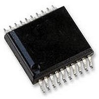
AS5134-ASSU austriamicrosystems, AS5134-ASSU Datasheet - Page 20

AS5134-ASSU
Manufacturer Part Number
AS5134-ASSU
Description
ENCODER, MAGNETIC, ROTARY, 8BIT, 20SSOP
Manufacturer
austriamicrosystems
Datasheet
1.AS5134-ASSU.pdf
(39 pages)
Specifications of AS5134-ASSU
Brief Features
9-Bit Multiturn Counter, User Programmable Zero Position And Sensitivity
Supply Voltage Range
4.5V To 5.5V
Operating Temperature Range
-40°C To +140°C
Digital Ic Case
RoHS Compliant
Ic Function
Programmable High Speed Magnetic Rotary Encoder
Rohs Compliant
Yes
AS5134
Data Sheet - D e t a i l e d D e s c r i p t i o n
READ ANA: Analog read out mode. The analog value of every OTP bit is available at pin 1 (PROG), which allows for
a verification of the fuse process. No data is available at the SSI.
tst: Test bits for internal testing
ID (59:42): Chip identifier to track the device in the field
hyst_2x (41): Increase the hysteresis two times (default = “0”, 2x = “1”)
FM (31): Fast mode → increase the oscillator frequency by 10%
lock_otp (21): To disable the programming of the factory bits – write access is still possible
r_add (20:17): The following OTP bits can be modified according to the requirements of the application.
r_bit (16): Redundancy bit (functionality is only implemented in the user region)
Sensitivity (15:14): Trim bit for the gain of the amplifier after the demodulator
abi (13:12): Mode selection for the incremental signals
uvw (11:9): Number of poles of the brush less dc motor - impact to the uvw signals
zero angle (8:0): Trim bit for the zero angle information
LP: Enables the low power mode to reduce the current consumption - digital registers are not reseted.
Notes:
AS5134 Programming
The AS5134 offers the following user programmable options:
This programming option allows the user to program any rotation angle of the magnet as the new zero position. This
useful feature simplifies the assembly process as the magnet does not need to be mechanically adjusted to the
electrical zero position. It can be assembled in any rotation angle and later matched to the mechanical zero position by
zero position programming. The 8,5-bit user programmable zero position can be applied both temporarily (command
WRITE OTP, #31) or permanently (command PROG OTP, #25).
This programming option allows the user to match the vertical distance of the magnet with the optimum magnetic field
range of the AS5134 by setting the sensitivity level. The 2-bit user programmable sensitivity setting can be applied
both temporarily (command WRITE OTP, #31) or permanently (command PROG OTP, #25).
Low Power Mode is a power saving mode with fast start-up. In Low Power Mode, all internal digital registers are frozen
and the power consumption is reduced to max. 1,5 mA. Start-up from this mode to normal operation can be
accomplished within 250µs. This mode is recommended for applications, where low power, but fast start-up and short
reading cycle intervals are required.
OTP Programming Connection
Programming of the AS5134 OTP memory does not require a dedicated programming hardware. The programming
can be simply accomplished over the serial 3-wire
6). For permanent programming (command PROG OTP, #25), a constant DC voltage of 8.0 – 8.5V (=100mA) must be
connected to pin 1 (PROG). For temporary OTP write (“soft write”; command WRITE OTP, #31), the programming
voltage is not required. The capacitors must be as close as possible to the pin, to ensure that a serial inductance of
50nH is not to be exceeded. The 50nH inductance could translate into a cable length of approximately 5cm.
www.austriamicrosystems.com
Zero Position Programming
Magnetic Field Optimization
Low Power Mode
1. Empty fields should be described with “logical 0”.
2. These bits will be deleted during power down or sleep mode to ensure that the user is able to detect that the
read out angle value is computed after the wake up sequence.
interface(see Figure 14)
Revision 1.8
or the optional 2-wire
interface(see Figure
20 - 39


