AD597AHZ Analog Devices Inc, AD597AHZ Datasheet - Page 4
AD597AHZ
Manufacturer Part Number
AD597AHZ
Description
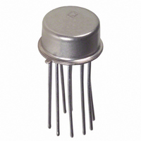
IC,TEMPERATURE SENSOR,BIPOLAR,CAN,10PIN,METAL
Manufacturer
Analog Devices Inc
Specifications of AD597AHZ
Rohs Compliant
YES
Function
Thermocouple Conditioner
Topology
Ice Point Compensation
Sensor Type
External
Sensing Temperature
-200°C ~ 1250°C
Output Type
Voltage
Output Alarm
Yes
Output Fan
No
Voltage - Supply
5 V ~ 30 V
Operating Temperature
-55°C ~ 125°C
Mounting Type
Through Hole
Package / Case
TO-100, Metal Can (10 Leads)
Bandwidth
15kHz
Supply Voltage Min
5V
Supply Voltage Max
30V
Digital Ic Case Style
SOIC
No. Of Pins
10
Operating Temperature Range
-55°C To +125°C
Svhc
No SVHC (15-Dec-2010)
Accuracy
4°C
Base Number
597
Lead Free Status / RoHS Status
Lead free / RoHS Compliant
Lead Free Status / RoHS Status
Lead free / RoHS Compliant


AD596/AD597
TEMPERATURE PROPORTIONAL OUTPUT MODE
The AD596/AD597 can be used to generate a temperature
proportional output of 10 mV/ C when operated with J and K
type thermocouples as shown in Figure 1. Thermocouples pro-
duce low level output voltages which are a function of both the
temperature being measured and the reference or cold junction
temperature. The AD596/AD597 compensates for the cold
junction temperature and amplifies the thermocouple signal to
produce a high level 10 mV/ C voltage output which is a func-
tion only of the temperature being measured. The temperature
stability of the part indicates the sensitivity of the output voltage
to changes in ambient or device temperatures. This is typically
0.02 C/ C over the +25 C to +100 C recommended ambient
temperature range. The parts will operate over the extended
ambient temperature ranges from –55 C to +125 C, but ther-
mocouple nonlinearity at the reference junction will degrade the
temperature stability over this extended range. Table I is a list of
ideal AD596/AD597 output voltages as a function of Celsius
temperature for type J and K ANSI standard thermocouples
with package and reference junction at 60 C. As is normally the
case, these outputs are subject to calibration and temperature
sensitivity errors. These tables are derived using the ideal trans-
fer functions:
The offsets and gains of these devices have been laser trimmed
to closely approximate thermocouple characteristics over mea-
surement temperature ranges centered around 175 C with the
AD596/AD597 at an ambient temperature between 25 C and
100 C. This eliminates the need for additional gain or offset
adjustments to make the output voltage read:
V
specified tolerances).
OUT
Figure 1. Temperature Proportional Output Connection
OPTIONAL
AD596 output = (Type J voltage + 301.5 V)
AD597 output = (Type K voltage)
CONSTANTAN
(ALUMEL)
IRON
(CHROMEL)
OFFSET
ADJUST
= 10 mV/ C
100k
100k
10k
–15V
+15V
1M
(thermocouple temperature in C) (within
0.01 F
AD597*
AD596/
*H PACKAGE PINOUT SHOWN
245.46
0 TO –25V
+5V TO +30V
0.01 F
V
+5V TO +30V
OUT
180.57
SPAN OF
–4–
Excluding calibration errors, the above transfer function is accu-
rate to within 1 C from +80 C to +550 C for the AD596 and
–20 C to +350 C for the AD597. The different temperature
ranges are due to the differences in J and K type thermocouple
curves.
European DIN FE-CuNi thermocouple vary slightly from ANSI
type J thermocouples. Table I does not apply when these types
of thermocouples are used. The transfer functions given previ-
ously and a thermocouple table should be used instead.
Figure 1 also shows an optional trimming network which can be
used to change the device’s offset voltage. Injecting or sinking
200 nA from Pin 3 will offset the output approximately 10 mV
(1 C).
The AD596/AD597 can operate from a single supply from 5 V
to 36 V or from split supplies totalling 36 V or less as shown.
Since the output can only swing to within 2 V of the positive
supply, the usable measurement temperature range will be re-
stricted when positive supplies less than 15 V for the AD597
and 10 V for the AD596 are used. If the AD596/AD597 is to be
used to indicate negative Celsius temperatures, then a negative
supply is required.
Common-mode voltages on the thermocouple inputs must
remain within the common-mode voltage range of the AD596/
AD597, with a return path provided for the bias currents. If the
thermocouple is not remotely grounded, then the dotted line
connection shown in Figure 1 must be made to one of the ther-
mocouple inputs. If there is no return path for the bias currents,
the input stage will saturate, causing erroneous output voltages.
In this configuration, the AD596/AD597 H package option has
circuitry which detects the presence of an open thermocouple. If
the thermocouple loop becomes open, one or both of the inputs
to the device will be deprived of bias current causing the output
to saturate. It is this saturation which is detected internally and
used to activate the alarm circuitry. The output of this feature
has a flexible format which can be used to source or sink up to
20 mA of current. The collector (+ALM) should not be allowed
to become more positive than (–V
permitted to be more positive than +V
(–ALM) should be constrained such that it does not become
more positive than 4 V below +V
used, this pin should be connected to Pins 4 or 5 as shown in
Figure 1. The alarm function is unavailable on the AR package
option.
S
S
. If the alarm feature is not
+ 36 V), however, it may be
S
. The emitter voltage
REV. B
Related parts for AD597AHZ
Image
Part Number
Description
Manufacturer
Datasheet
Request
R

Part Number:
Description:
±1.7g Dual-Axis IMEMS Accelerometer Evaluation Board
Manufacturer:
Analog Devices Inc
Datasheet:

Part Number:
Description:
Inertial Sensor Evaluation System
Manufacturer:
Analog Devices Inc
Datasheet:
Part Number:
Description:
Manufacturer:
Analog Devices Inc
Datasheet:
Part Number:
Description:
Manufacturer:
Analog Devices Inc
Datasheet:
Part Number:
Description:
Manufacturer:
Analog Devices Inc
Datasheet:
Part Number:
Description:
Manufacturer:
Analog Devices Inc
Datasheet:
Part Number:
Description:
Manufacturer:
Analog Devices Inc
Datasheet:
Part Number:
Description:
Manufacturer:
Analog Devices Inc
Datasheet:
Part Number:
Description:
Manufacturer:
Analog Devices Inc
Datasheet:
Part Number:
Description:
Manufacturer:
Analog Devices Inc
Datasheet:
Part Number:
Description:
Manufacturer:
Analog Devices Inc
Datasheet:
Part Number:
Description:
Manufacturer:
Analog Devices Inc
Datasheet:
Part Number:
Description:
Manufacturer:
Analog Devices Inc
Datasheet: