AD597AHZ Analog Devices Inc, AD597AHZ Datasheet - Page 6
AD597AHZ
Manufacturer Part Number
AD597AHZ
Description
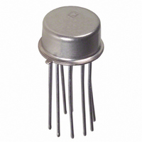
IC,TEMPERATURE SENSOR,BIPOLAR,CAN,10PIN,METAL
Manufacturer
Analog Devices Inc
Specifications of AD597AHZ
Rohs Compliant
YES
Function
Thermocouple Conditioner
Topology
Ice Point Compensation
Sensor Type
External
Sensing Temperature
-200°C ~ 1250°C
Output Type
Voltage
Output Alarm
Yes
Output Fan
No
Voltage - Supply
5 V ~ 30 V
Operating Temperature
-55°C ~ 125°C
Mounting Type
Through Hole
Package / Case
TO-100, Metal Can (10 Leads)
Bandwidth
15kHz
Supply Voltage Min
5V
Supply Voltage Max
30V
Digital Ic Case Style
SOIC
No. Of Pins
10
Operating Temperature Range
-55°C To +125°C
Svhc
No SVHC (15-Dec-2010)
Accuracy
4°C
Base Number
597
Lead Free Status / RoHS Status
Lead free / RoHS Compliant
Lead Free Status / RoHS Status
Lead free / RoHS Compliant


AD596/AD597
SINGLE AND DUAL SUPPLY CONNECTIONS
In the single supply configuration as used in the setpoint con-
troller of Figure 2, any convenient voltage from +5 V to +36 V
may be used, with self-heating errors being minimized at lower
supply levels. In this configuration, the –V
is tied to ground. Temperatures below zero can be accommo-
dated in the single supply setpoint mode, but not in the single
supply temperature measuring mode (Figure 1 reconnected for
single supply). Temperatures below zero can only be indicated
by a negative output voltage, which is impossible in the single
supply mode.
Common-mode voltages on the thermocouple inputs must
remain below the positive supply, and not more than 0.15 V
more negative than the minus supply. In addition, a return path
for the input bias currents must be provided. If the thermo-
couple is not remotely grounded, then the dotted line connec-
tions in Figures 1 and 2 are mandatory.
STABILITY OVER TEMPERATURE
The AD596/AD597 is specified for a maximum error of 4 C at
an ambient temperature of 60 C and a measuring junction
temperature at 175 C. The ambient temperature stability is
specified to be a maximum of 0.05 C/ C. In other words, for
every degree change in the ambient temperature, the output will
change no more than 0.05 degrees. So, at 25 C the maximum
deviation from the temperature-voltage characteristic of Table I
is 5.75 C, and at 100 C it is 6 C maximum (see Figure 5). If
the offset error of 4 C is removed with a single offset adjust-
ment, these errors will be reduced to 1.75 C and 2 C max.
The optional trim circuit shown in Figure 1 demonstrates how
the ambient offset error can be adjusted to zero.
THERMAL ENVIRONMENTAL EFFECTS
The inherent low power dissipation of the AD596/AD597 keeps
self-heating errors to a minimum. However, device output is
capable of delivering 5 mA to an external load and the alarm
circuitry can supply up to 20 mA. Since the typical junction to
ambient thermal resistance in free air is 150 C/W, significant
temperature difference between the package pins (where the
reference junction is located) and the chip (where the cold junc-
tion temperature is measured and then compensated) can exist
when the device is operated in a high dissipation mode. These
+1.75 C
–1.75 C
+2.0 C
+0.8 C
–0.8 C
–2.0 C
0
25 C
TYPICAL
Figure 5. Drift Error vs. Temperature
MAXIMUM
MAXIMUM
60 C
S
connection at Pin 5
100 C
–6–
temperature differences will result in a direct error at the out-
put. In the temperature proportional mode, the alarm feature
will only activate in the event of an open thermocouple or sys-
tem transient which causes the device output to saturate.
Self-Heating errors will not effect the operation of the alarm but
two cases do need to be considered. First, after a fault is cor-
rected and the alarm is reset, the AD596/AD597 must be al-
lowed to cool before readings can again be accurate. This can
take 5 minutes or more depending upon the thermal environ-
ment seen by the device. Second, the junction temperature of
the part should not be allowed to exceed 150 C. If the alarm
circuit of the AD596/AD597 is made to source or sink 20 mA
with 30 V across it, the junction temperature will be 90 C above
ambient causing the die temperature to exceed 150 C when
ambient is above 60 C. In this case, either the load must be
reduced, or a heat sink used to lower the thermal resistance.
TEMPERATURE READOUT AND CONTROL
Figure 6 shows a complete temperature indication and control
system based on the AD596/AD597. Here the AD596/AD597 is
being used as a closed-loop thermocouple signal conditioner
and an external op amp is used to implement setpoint. This has
two important advantages. It provides a high level (10 mV/ C)
output for the A/D panel meter and also preserves the alarm
function for open thermocouples.
The A/D panel meter can easily be offset and scaled as shown to
read directly in degrees Fahrenheit. If a two temperature cali-
bration scheme is used, the dominant residual errors will arise
from two sources; the ambient temperature rejection (typically
earity typical +1 C from 80 C to 550 C for type J and +1 C
from –20 C to 350 C for type K.
An external voltage reference is used both to increase the stabil-
ity of the A/D converter and supply a stable reference for the
setpoint voltage.
A traditional requirement for the design of setpoint control
thermocouple systems has been to configure the system such
that the appropriate action is taken in the event of an open
thermocouple. The open thermocouple alarm pin with its flex-
ible current-limited output format supports this function when
the part operates in the temperature proportional mode. In
addition, if the thermocouple is not remotely grounded, it is
possible to program the device for either a positive or negative
full-scale output in the event of an open thermocouple. This is
done by connecting the bias return resistor directly to Pin 1 if a
high output voltage is desired to indicate a fault condition. Al-
ternately, if the bias return is provided on the thermocouple lead
connected to Pin 2, an open circuit will result in an output low
reading. Figure 6 shows the ground return connected to Pin 1
so that if the thermocouple fails, the heater will remain off. At
the same time, the alarm circuit lights the LED signalling the
need to service the thermocouple. Grounding Pin 2 would lead
to low output voltage saturation, and in this circuit would result
in a potentially dangerous thermal runaway under fault conditions.
2 C over a 25 C to 100 C range) and thermocouple nonlin-
REV. B
Related parts for AD597AHZ
Image
Part Number
Description
Manufacturer
Datasheet
Request
R

Part Number:
Description:
±1.7g Dual-Axis IMEMS Accelerometer Evaluation Board
Manufacturer:
Analog Devices Inc
Datasheet:

Part Number:
Description:
Inertial Sensor Evaluation System
Manufacturer:
Analog Devices Inc
Datasheet:
Part Number:
Description:
Manufacturer:
Analog Devices Inc
Datasheet:
Part Number:
Description:
Manufacturer:
Analog Devices Inc
Datasheet:
Part Number:
Description:
Manufacturer:
Analog Devices Inc
Datasheet:
Part Number:
Description:
Manufacturer:
Analog Devices Inc
Datasheet:
Part Number:
Description:
Manufacturer:
Analog Devices Inc
Datasheet:
Part Number:
Description:
Manufacturer:
Analog Devices Inc
Datasheet:
Part Number:
Description:
Manufacturer:
Analog Devices Inc
Datasheet:
Part Number:
Description:
Manufacturer:
Analog Devices Inc
Datasheet:
Part Number:
Description:
Manufacturer:
Analog Devices Inc
Datasheet:
Part Number:
Description:
Manufacturer:
Analog Devices Inc
Datasheet:
Part Number:
Description:
Manufacturer:
Analog Devices Inc
Datasheet: