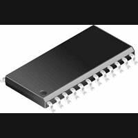
LM2577M-ADJ National Semiconductor, LM2577M-ADJ Datasheet - Page 24

LM2577M-ADJ
Manufacturer Part Number
LM2577M-ADJ
Description
DC/DC Converter IC
Manufacturer
National Semiconductor
Datasheet
1.LM2577M-ADJ.pdf
(31 pages)
Specifications of LM2577M-ADJ
Input Voltage
40V
Output Voltage
37V
No. Of Pins
24
Operating Temperature Range
-40°C To +125°C
Termination Type
SMD
Mounting Type
Surface Mount
Voltage Regulator Type
Boost Switching
Lead Free Status / RoHS Status
Contains lead / RoHS non-compliant
Available stocks
Company
Part Number
Manufacturer
Quantity
Price
Company:
Part Number:
LM2577M-ADJ
Manufacturer:
NS
Quantity:
230
Part Number:
LM2577M-ADJ
Manufacturer:
NS/国半
Quantity:
20 000
Part Number:
LM2577M-ADJ/NOPB
Manufacturer:
NS/国半
Quantity:
20 000
www.national.com
Application Hints
step-up regulator, and this requires a larger bypass capacitor
to decouple the LM1577/LM2577 V
most applications, a low ESR, 1.0 µF cap will be sufficient, if
it is connected very close to the V
In addition to this bypass cap, a larger capacitor (≥ 47 µF)
should be used where the flyback transformer connects to
the input supply. This will attenuate noise which may inter-
fere with other circuits connected to the same input supply
voltage.
6. Snubber Circuit
A “snubber” circuit is required when operating from input
voltages greater than 10V, or when using a transformer with
L
transformer primary that occurs immediately after the output
switch turns off. Without it, the switch voltage may exceed
the 65V maximum rating. As shown in Figure 21, the snub-
P
Transformer
1
2
3
FIGURE 20. Flyback Transformer Selection Guide
≥ 200 µH. This circuit clamps a voltage spike from the
Transformer
Type
L
L
L
1
2
3
Type
P
P
P
N = 0.5
N = 0.5
= 100 µH
= 200 µH
= 250 µH
N = 1
326-0637
330-0202
330-0203
Manufacturers’ Part Numbers
AIE
Voltage
Input
10V
10V
10V
12V
12V
12V
15V
15V
15V
5V
5V
5V
(Continued)
IN
PE-65300
PE-65301
PE-65302
IN
Pulse
and Ground pins.
Voltage
pin from this noise. For
Output
±
±
±
±
±
±
±
±
±
±
±
±
Dual
10V
12V
15V
10V
12V
15V
10V
12V
15V
10V
12V
15V
Maximum
RL-2580
RL-2581
RL-2582
Current
325 mA
275 mA
225 mA
700 mA
575 mA
500 mA
800 mA
700 mA
575 mA
900 mA
825 mA
700 mA
Output
Renco
24
ber consists of a fast recovery diode, and a parallel RC. The
RC values are selected for switch clamp voltage (V
that is 5V to 10V greater than V
equations to calculate R and C;
Power dissipation (and power rating) of the resistor is;
The fast recovery diode must have a reverse voltage rating
greater than V
FLYBACK REGULATOR CIRCUIT EXAMPLE
The circuit of Figure 22 produces
from a single 5V input. The output regulation of this circuit is
shown in Figure 23 and Figure 25, while the load transient
response is shown in Figure 24 and Figure 26. Switching
waveforms seen in this circuit are shown in Figure 27.
CLAMP
FIGURE 21. Snubber Circuit
.
SW(OFF)
±
15V (at 225 mA each)
. Use the following
01146819
CLAMP
)


