LM2586T-3.3 National Semiconductor, LM2586T-3.3 Datasheet - Page 27
LM2586T-3.3
Manufacturer Part Number
LM2586T-3.3
Description
Power Supply IC
Manufacturer
National Semiconductor
Specifications of LM2586T-3.3
Output Current
3A
Output Voltage
3.3VDC
No. Of Pins
7
Peak Reflow Compatible (260 C)
No
Termination Type
Through Hole
Leaded Process Compatible
No
Mounting Type
Through Hole
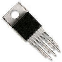
Package / Case
7-TO-220
Lead Free Status / RoHS Status
Contains lead / RoHS non-compliant


Application Hints
range in value between 10Ω and 1 kΩ, and the capacitor will
vary from 0.001 µF to 0.1 µF. Adding a snubber will (slightly)
reduce the efficiency of the overall circuit.
The other method to reduce or eliminate the “ringing” is to
insert a Schottky diode clamp between pins 5 and 4
(ground), also shown in Figure 43. This prevents the voltage
at pin 5 from dropping below −0.4V. The reverse voltage
rating of the diode must be greater than the switch off
voltage.
OUTPUT VOLTAGE LIMITATIONS
The maximum output voltage of a boost regulator is the
maximum switch voltage minus a diode drop. In a flyback
regulator, the maximum output voltage is determined by the
turns ratio, N, and the duty cycle, D, by the equation:
The duty cycle of a flyback regulator is determined by the
following equation:
CIRCUIT LAYOUT GUIDELINES
As in any switching regulator, layout is very important. Rap-
idly switching currents associated with wiring inductance
generate voltage transients which can cause problems. For
FIGURE 44. Input Line Filter
V
OUT
≈ N x V
IN
(Continued)
x D/(1 − D)
FIGURE 45. Circuit Board Layout
01251663
27
Theoretically, the maximum output voltage can be as large
as desired — just keep increasing the turns ratio of the trans-
former. However, there exists some physical limitations that
prevent the turns ratio, and thus the output voltage, from
increasing to infinity. The physical limitations are capaci-
tances and inductances in the LM2586 switch, the output
diode(s), and the transformer — such as reverse recovery
time of the output diode (mentioned above).
NOISY INPUT LINE CONDITION
A small, low-pass RC filter should be used at the input pin of
the LM2586 if the input voltage has an unusually large
amount of transient noise, such as with an input switch that
bounces. The circuit in Figure 44 demonstrates the layout of
the filter, with the capacitor placed from the input pin to
ground and the resistor placed between the input supply and
the input pin. Note that the values of R
the schematic are good enough for most applications, but
some readjusting might be required for a particular applica-
tion. If efficiency is a major concern, replace the resistor with
a small inductor (say 10 µH and rated at 200 mA).
STABILITY
All current-mode controlled regulators can suffer from an
instability, known as subharmonic oscillation, if they operate
with a duty cycle above 50%. To eliminate subharmonic
oscillations, a minimum value of inductance is required to
ensure stability for all boost and flyback regulators. The
minimum inductance is given by:
where V
found in the Characteristic Curves.
minimal inductance and ground loops, keep the length of the
leads and traces as short as possible. Use single point
grounding or ground plane construction for best results.
Separate the signal grounds from the power grounds (as
SAT
is the switch saturation voltage and can be
IN
01251664
and C
IN
www.national.com
shown in
Related parts for LM2586T-3.3
Image
Part Number
Description
Manufacturer
Datasheet
Request
R

Part Number:
Description:
Manufacturer:
National Semiconductor
Datasheet:

Part Number:
Description:
DC/DC Converter IC
Manufacturer:
National Semiconductor
Datasheet:

Part Number:
Description:
IC REG SIMPLE SWITCHER TO-220-7
Manufacturer:
National Semiconductor
Datasheet:
Part Number:
Description:
IC REG SIMPLE SWITCHER TO220-7
Manufacturer:
National Semiconductor
Datasheet:
Part Number:
Description:
IC REG SIMPLE SWITCHER TO-220-7
Manufacturer:
National Semiconductor
Datasheet:
Part Number:
Description:
IC MULTI CONFIG SYNC 12V TO220-7
Manufacturer:
National Semiconductor
Datasheet:

Part Number:
Description:
National Semiconductor [8-Bit D/A Converter]
Manufacturer:
National Semiconductor
Datasheet:
Part Number:
Description:
National Semiconductor [Media Coprocessor]
Manufacturer:
National Semiconductor
Datasheet:
Part Number:
Description:
Digitally Controlled Tone and Volume Circuit with Stereo Audio Power Amplifier, Microphone Preamp Stage and National 3D Sound
Manufacturer:
National Semiconductor
Datasheet:
Part Number:
Description:
Digitally Controlled Tone and Volume Circuit with Stereo Audio Power Amplifier, Microphone Preamp Stage and National 3D Sound
Manufacturer:
National Semiconductor
Datasheet:
Part Number:
Description:
AC97 Rev 2 Codec with Sample Rate Conversion and National 3D Sound
Manufacturer:
National Semiconductor
Part Number:
Description:
Manufacturer:
National Semiconductor
Datasheet:
Part Number:
Description:
Manufacturer:
National Semiconductor
Datasheet: