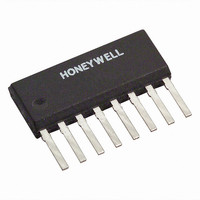
HMC1021Z Honeywell Microelectronics & Precision Sensors, HMC1021Z Datasheet - Page 8

HMC1021Z
Manufacturer Part Number
HMC1021Z
Description
SENSOR LINEAR MAGN 1 AXIS 8-SIP
Manufacturer
Honeywell Microelectronics & Precision Sensors
Type
Linearr
Datasheet
1.HMC1021S.pdf
(15 pages)
Specifications of HMC1021Z
Rohs Status
RoHS non-compliant
Sensing Range
±6g
Voltage - Supply
5 V ~ 25 V
Output Type
Differential Voltage
Features
Compass - One Axis
Operating Temperature
-55°C ~ 150°C
Package / Case
8 Pin SIP
Operating Supply Voltage (typ)
5V
Current - Supply
-
Current - Output (max)
-
Lead Free Status / Rohs Status
Not Compliant
Other names
342-1004-5
Available stocks
Company
Part Number
Manufacturer
Quantity
Price
Company:
Part Number:
HMC1021Z
Manufacturer:
honeywell
Quantity:
12 800
Company:
Part Number:
HMC1021ZRC
Manufacturer:
Honeywell
Quantity:
5 000
HMC1001/1002/1021/1022
SET/RESET STRAP OPERATION
The reasons to perform a set or reset on an AMR sensor are: 1) To recover from a strong external magnetic field that
likely has re-magnetized the sensor, 2) to optimize the magnetic domains for most sensitive performance, and 3) to flip
the domains for extraction of bridge offset under changing temperature conditions.
Strong external magnetic fields that exceed a 10 to 20 gauss “disturbing field” limit, can come from a variety of sources.
The most common types of strong field sources come from permanent magnets such as speaker magnets, nearby high-
current conductors such as welding cables and power feeder cables, and by magnetic coils in electronic equipment such
as CRT monitors and power transformers. Magnets exhibit pole face strengths in hundreds to thousands of gauss. These
high intensity magnetic field sources do not permanently damage the sensor elements, but the elements will be disturbed
to the exposed fields rather than the required easy axis directions. The result of this re-magnetization of the sensor
elements, the sensor will lack sensitivity or indicate a “stuck” sensor output. Using the set and reset pulses will
magnetically “restore” the sensor.
AMR sensors are also ferromagnetic devices with a crystalline structure. This same thin film structure that makes the
sensor sensitive to external magnetic fields also has the downside that changing magnetic field directions and thermal
energy over time will increase the self-noise of the sensor elements. This noise, while very small, does impair the
accurate measurement of sub-milligauss field strengths or changes in field strength in microgauss increments. By
employing frequent set and reset fields on the sensor, the self-noise will be to its lowest possible level.
As the sensor element temperature changes, either due to self-heating or external environments, each element’s
resistance will change in proportion to the temperature. One way to eliminate the bridge offset voltage is to make stable
magnetic field measurements of the bridge output voltage in between each set and reset field application. Since the
external field components of the bridge output voltage will flip polarity, the set and reset bridge output voltages can be
subtracted and the result divided by two to calculate the bridge offset. See application note AN212 for the details on
bridge offset voltage computation and correction.
SET/RESET DRIVE CIRCUITS
The above description explained that providing pulses of electrical current creates the needed magnetic fields to realign
the magnetic domains of the sensor resistive elements. Also the rationale for performing these set and reset pulses has
been justified. The following paragraphs shall show when and how to apply these pulsed currents, and circuits to
implement them. Figure 2 shows a simplistic schematic of a set/reset circuit.
These set and reset pulses are shown in Figure 2 as dampened exponential pulse waveforms because the most popular
method of generating these relatively high current, short duration pulses is via a capacitive “charge and dump” type of
circuit. Most electronics, especially in consumer battery powered devices, do not have the capability to supply these high
current pulses from their existing power supply sources. Thus “Vsr” is actually a charged up capacitor that is suddenly
switched across the set/reset strap. The value of this capacitor is usually a couple hundred nano-Farads ( F) to a few
micro-Farads ( F) depending on the strap resistance to be driven. The decay of the exponential waveform will mostly be
governed by a time constant ( or Tau) that is the capacitance in farads multiplied by the resistance, and is measured in
seconds.
8
1
1
Figure 2 – A Simple Set/Reset Circuit
Pulse Source
Pulse Source
Set/Reset
Set/Reset
Iset
Iset
Vsr
Vsr
= R*C = ~2 sec
= R*C = ~2 sec
Ireset
Ireset
S/R+
S/R+
S/R-
S/R-
Rsr
Rsr
5
5
Resistance
Resistance
Strap
Strap
www.honeywell.com


