71A30-10-1-02N Grayhill Inc, 71A30-10-1-02N Datasheet - Page 13
71A30-10-1-02N
Manufacturer Part Number
71A30-10-1-02N
Description
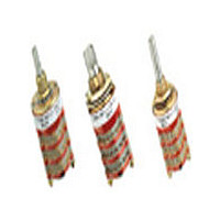
Rotary Switch, 1/8" Shaft, 30°
Manufacturer
Grayhill Inc
Datasheet
1.71A30-10-1-02N.pdf
(14 pages)
Specifications of 71A30-10-1-02N
Total # Of Positions
2
Pole Throw Configuration
SPDT
Actuator Style
Shaft
Actuator Material
Stainless Steel
Current Rating (max)
0.25A
Illumination Type
Not Required
Ac Voltage Rating (max)
115VVAC
Dc Voltage Rating (max)
30VVDC
Contact Material
Silver Alloy/Beryllium Copper
Product Height (mm)
93.73mm
Product Depth (mm)
19.05mm
Product Length (mm)
19.05mm
Mounting Style
Panel
Terminal Type
Solder Lug
Lead Free Status / Rohs Status
Compliant


1
use AJ instead of number of positions when
ordering.
2
4 operative decks have an additional spacer
deck after deck 2. Use total decks to calculate
CHOICES AND LIMITATIONS: Series 71
A =
B =
E = Metric Mount Shaft & Bushing
D = Adjustable Stops (Adj. Stop)
S = Shaft and Panel Seal (S/P Seal)
Rotary
For Adjustable Stop styles (with the letter D),
Military Qualified PC mount switches of 3 or
14
Basic Style
1
1
/
/
8
4
" Diameter Shaft
" Diameter Shaft
A
B
E
AF
BF
EF
BT
MA
MB
MAF
MBF
C
CF
Grayhill, Inc. • 561 Hillgrove Avenue • LaGrange, Illinois
Style Choices
With S/P Seal
Multi-Deck Rotary Switches
AS
BS
ES
ASF
BSF
ESF
——
MAS
MBS
MASF
MBSF
——
——
Adj. Stop
AD
BD
ED
ADF
BDF
EDF
——
——
——
——
——
——
——
F = PC Mount Terminals
T = PC Mount Terminals and Process Sealed
M = Military
length; but use only the number of operative
decks when creating the part number.
3
specify Fixed stop after last position or
Continuous rotation when ordering. (Note: 1 p,
71BT, 10 positions, is available only as
Continuous).
For 1-pole switches with maximum positions,
Switching Decks & Bushing; no panel seal
All switches without F or T have solder lugs
Angle of
Throw
30°
36°
30°
36°
36°
30°
36°
30°
36°
30°
36°
30°
36°
60525-5997 • USA • Phone: 708-354-1040 • Fax: 708-354-2820 • www.grayhill.com
01 thru 12
01 thru 08
01 thru 05
01 thru 04
01 thru 03
01 or 02
01 thru 12
01 thru 08
01 thru 12
01 thru 08
01 thru 12
01 thru 08
01 thru 05
01 thru 05
01 thru 05
01 thru 05
01 thru 05
01 thru 04
01 thru 02
01 thru 05
01 thru 05
01 thru 04
01 thru 04
01 thru 04
01 thru 04
01 thru 03
01 thru 03
01 or 02
01
01
01
01 thru 03
01 thru 03
01 thru 03
01 thru 03
01 thru 03
01 thru 03
No. Of
Decks
4
4
4
4
4
4
4
2,4
2,4
2,4
2,4
Per Deck
Poles
1
2
3
4
5
6
1
2
1
2
1
2
1
2
1
2
3
4
6
1
2
1
2
1
2
1
2
3
4
5
6
1
2
1
2
1
2
5
5
4
decks; PC mount–4 decks), Grayhill can pro-
vide switches with additional decks in the
materials of the ‘M’ style. Contact Grayhill.
5
deck are not available with adjustable stops.
Switches in 30° throw with 5 or 6 poles per
In addition to qualified types (Solder lug–5
C = Concentric Shaft
2 Switches with same Style and Angle of
Throw, one behind the other.
Limits below apply to either switch section
(A or B).
Positions
Per Pole
02 thru 12
02 thru 06
02 thru 04
02 or 03
02
02
02 thru 10
02 thru 05
02 thru 12
02 thru 06
02 thru 10
02 thru 05
02 thru 10
02 thru 05
02 thru 12
02 thru 06
02 thru 04
02 or 03
02
02 thru 10
02 thru 05
02 thru 12
02 thru 06
02 thru 10
02 thru 05
02 thru 12
02 thru 06
02 thru 04
02 or 03
02
02
02 thru 10
02 thru 05
02 thru 12
02 thru 06
02 thru 10
02 thru 05
1
3
3
3
3
3
3
3
3
3
3
3
3
3
Non-Shorting
Shorting Or
N or S
N or S
N or S
N or S
N or S
N or S
N or S
N or S
N or S
N or S
N or S
N or S
N or S
N or S
N or S
N or S
N or S
N or S
N or S
N or S
N or S
N or S
N or S
N or S
N or S
N or S
N or S
N or S
N or S
N or S
N or S
N or S
N or S
N or S
N or S
N or S
N or S
Related parts for 71A30-10-1-02N
Image
Part Number
Description
Manufacturer
Datasheet
Request
R

Part Number:
Description:
GRAYHILL,SERIES 71,ROTARY SWITCH,1/8 SHAFT,30DEGREE,DECK,1 POLE/DECK,12POSITION/POLE,NON-SHORTING,CONTINUOUS .
Manufacturer:
Grayhill Inc

Part Number:
Description:
Rotary Switch, 1/8" Shaft, 30°
Manufacturer:
Grayhill Inc
Datasheet:
Part Number:
Description:
Rotary Switch, 1/8" Shaft, 30°
Manufacturer:
Grayhill Inc
Datasheet:
Part Number:
Description:
Rotary Switch, 1/8" Shaft, 30°
Manufacturer:
Grayhill Inc
Datasheet:
Part Number:
Description:
71A30-01-1-11S Deg
Manufacturer:
Grayhill Inc
Datasheet:
Part Number:
Description:
71A30-01-5-02N Deg
Manufacturer:
Grayhill Inc
Datasheet:
Part Number:
Description:
71A30-02-2-04S Deg
Manufacturer:
Grayhill Inc
Datasheet:
Part Number:
Description:
71A30-04-3-02N Deg
Manufacturer:
Grayhill Inc
Datasheet: