71A30-10-1-02N Grayhill Inc, 71A30-10-1-02N Datasheet - Page 7
71A30-10-1-02N
Manufacturer Part Number
71A30-10-1-02N
Description
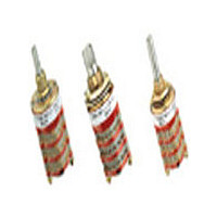
Rotary Switch, 1/8" Shaft, 30°
Manufacturer
Grayhill Inc
Datasheet
1.71A30-10-1-02N.pdf
(14 pages)
Specifications of 71A30-10-1-02N
Total # Of Positions
2
Pole Throw Configuration
SPDT
Actuator Style
Shaft
Actuator Material
Stainless Steel
Current Rating (max)
0.25A
Illumination Type
Not Required
Ac Voltage Rating (max)
115VVAC
Dc Voltage Rating (max)
30VVDC
Contact Material
Silver Alloy/Beryllium Copper
Product Height (mm)
93.73mm
Product Depth (mm)
19.05mm
Product Length (mm)
19.05mm
Mounting Style
Panel
Terminal Type
Solder Lug
Lead Free Status / Rohs Status
Compliant


SERIES 71
0.5 to 0.75" Diameter, 1/4 Amp,
Concentric Shaft
FEATURES
• Two Switches in the Panel Space
DIMENSIONS
CIRCUIT DIAGRAMS: Solder Lug Terminals
ADD-A-POT SWITCHES
Contact Grayhill for Series 71 Concentric Add-A-Pot or Add-A-Switch type switches.
Rotary
of a Single Shaft Rotary
Solder Lug Terminals: Style C
36° Angle
of Throw
8
30° Angle
of Throw
Angle C is 15° in 12 position switches and 36 ° in 10 position switches.
Sec. A
1
2
3
1
2
3
1
2
3
(17,45 ± 0,38)
No. of Decks
.687 ± .015
Grayhill, Inc. • 561 Hillgrove Avenue • LaGrange, Illinois
C L
DIA.
C
C
OF POSITION NO. 1
L
L
OF BUSHING KEYWAY
.094 ± .010
(2,39 ± 0,25)
.219 ± .004
(5,56 ± 0,10)
Sec. B
1
1
1
2
2
2
3
3
3
In inches (and millimeters)
6
7
SEE
CHART
5
8
C
Dimension A
1.415 (35,94)
1.633 (41,49)
2.131 (54,13)
1.633 (41,49)
2.131 (54,13)
2.349 (59,66)
2.131 (54,13)
2.349 (59,66)
2.567 (65,20)
ONE POLE
Multi-Deck Rotary Switches
4
9
10
3
Grayhill part number and date code marked on detent cover label. Customer part number marked on request.
11
2
12
C
.125 + .001
–.002 DIA.
(3,18 + 0,25
–0,05)
1
.250 ± .020
(6,35 ± 0,05)
L
.375 ± .020
(9,53 ± 0,05)
OF
BUSHING
KEYWAY
C1
Dimension B
.032 (0,81)
.032 (0,81)
.312 (7,92)
.032 (0,81)
.312 (7,92)
.312 (7,92)
.312 (7,92)
.312 (7,92)
.312 (7,92)
BUSHING KEYWAY
.066 ± .002 (1,68 ± 0,05) WIDE BY
.036 ± .003 (0,91 ± 0,08) DEEP
FROM A .375 (9,53) DIA.
C2
3/8-32UNEF-2A
THREAD
5
6
4
.250 + .001
–.002
(6,35 + 0,03
–0,05)
DIA.
Switch is Viewed From Shaft End and Shown in Position No. 1.
6
7
ONE POLE
5
8
7
TWO POLE
3
Approx.
.312 ± .020
(7,92 ± 0,51)
Weight
Grams
4
9
24
26
28
26
28
30
28
30
32
Note: All common terminals are located above base terminals as shown.
8
2
10
3
9
1
10
C L OF
11
2
BUSHING
KEYWAY
C1
1
12
60525-5997 • USA • Phone: 708-354-1040 • Fax: 708-354-2820 • www.grayhill.com
C1
C L
CONTROLLED
(0,86 ± 0,08)
BY .250 (6,35)
.034 ± .003
DIA. SHAFT
SECTION
STUD PROJECTION
DIM. A ± .046 (1,17)
Terminal Detail
6
7
C2
5
A
8
C2
5
THREE POLE
4
C3
DIM. B REF.
6
4
9
TWO POLE
CONTROLLED
SECTION
7
BY .125 (3,18)
3
DIA. SHAFT
10
3
B
11
2
8
2
12
1
.068 ± .005
(1,73 ± 0,13)
1
9
C1
10
C
C1
L
C L
C3
.562
± .015
(14,27
± 0,38)
6
7
5
8
FOUR POLE
C2
4
9
Note: Common location for a single pole per
SEE NOTE
SEE NOTE
3
SEE
DETAIL
10 11
SEE
DETAIL
C4
deck switch. For common location on
multipole switches see circuit diagrams.
30° and 36° Angle of Throw may be
interposed on either shaft diameter.
2
1
12
36° Angle of Throw
30° Angle of Throw
C1
C
L
OVER TERMINALS
OVER TERMINALS
Rear Views
C4
(19,05 ± 0,51)
(12,7 ± 0,38)
(19,05 ± 0,51)
(12,7 ± 0,38)
.500 ± .015
.500 ± .015
.750 ± .020
.750 ± .020
C3
6
FIVE OR SIX POLE
DIA.
7
DIA.
5
8
C5
4
9
3
10
C2
11
2
C6
1
12
C1
C
L
Related parts for 71A30-10-1-02N
Image
Part Number
Description
Manufacturer
Datasheet
Request
R

Part Number:
Description:
GRAYHILL,SERIES 71,ROTARY SWITCH,1/8 SHAFT,30DEGREE,DECK,1 POLE/DECK,12POSITION/POLE,NON-SHORTING,CONTINUOUS .
Manufacturer:
Grayhill Inc

Part Number:
Description:
Rotary Switch, 1/8" Shaft, 30°
Manufacturer:
Grayhill Inc
Datasheet:
Part Number:
Description:
Rotary Switch, 1/8" Shaft, 30°
Manufacturer:
Grayhill Inc
Datasheet:
Part Number:
Description:
Rotary Switch, 1/8" Shaft, 30°
Manufacturer:
Grayhill Inc
Datasheet:
Part Number:
Description:
71A30-01-1-11S Deg
Manufacturer:
Grayhill Inc
Datasheet:
Part Number:
Description:
71A30-01-5-02N Deg
Manufacturer:
Grayhill Inc
Datasheet:
Part Number:
Description:
71A30-02-2-04S Deg
Manufacturer:
Grayhill Inc
Datasheet:
Part Number:
Description:
71A30-04-3-02N Deg
Manufacturer:
Grayhill Inc
Datasheet: