71A30-10-1-02N Grayhill Inc, 71A30-10-1-02N Datasheet - Page 5
71A30-10-1-02N
Manufacturer Part Number
71A30-10-1-02N
Description
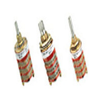
Rotary Switch, 1/8" Shaft, 30°
Manufacturer
Grayhill Inc
Datasheet
1.71A30-10-1-02N.pdf
(14 pages)
Specifications of 71A30-10-1-02N
Total # Of Positions
2
Pole Throw Configuration
SPDT
Actuator Style
Shaft
Actuator Material
Stainless Steel
Current Rating (max)
0.25A
Illumination Type
Not Required
Ac Voltage Rating (max)
115VVAC
Dc Voltage Rating (max)
30VVDC
Contact Material
Silver Alloy/Beryllium Copper
Product Height (mm)
93.73mm
Product Depth (mm)
19.05mm
Product Length (mm)
19.05mm
Mounting Style
Panel
Terminal Type
Solder Lug
Lead Free Status / Rohs Status
Compliant


SERIES 71: PC Board Pattern In inches (and millimeters)
SERIES 71: PC MOUNT ACCESSORY
Rotary
1
In inches (and millimeters)
All Styles Except 71BT
/
6
8
" and
(6,48 ± 0,05) DIA.
.255 ±.002
0.030 ±.001
(0,76 ± 0,03)
Grayhill, Inc. • 561 Hillgrove Avenue • LaGrange, Illinois
1
/
.207 ±.005
(5,26 ± 0,13)
4
For printed circuit styles. Mounting bushing provides additional
support for the front end of the switch. Order separately by
appropriate part number. Rotary switch discount applies.
Spacer decks can be supplied to facilitate PC board layouts of
three or more decks. A spacer deck does not have any
terminals and provides no switching function. Dimensionally, it
requires the same space as one normal switch deck. Spacer
deck can be placed at any location in the switch, per your
instructions. Switches which include spacer decks are procured
under a special part number.
" Diameter Shaft Styles
FOR USE WITH
PART 71C2054
STYLE AF
COMMON TERMINAL HOLE
B
30° Angle of Throw
LOCATION (SEE CHART)
Multi-Deck Rotary Switches
.075
(1,91)
TYP.
DIMENSIONS APPLY TO BOTH WASHERS.
SHAFT END
OF SWITCH
(3,30 ± 0,08)
0.368 ± .003
(9,35 ± 0,08)
.130 ±.003
.032 (0,81) THICK
.037 (0,94)
(7,62)
.300
TYP.
WASHER IS
C
L
A
.110 TYP.
.110 (2,79 )TYP.
FOR USE WITH
PART 71C2053
(2,79 )
STYLE BF
.500
±.002
(12,7
± 0,05)
60525-5997 • USA • Phone: 708-354-1040 • Fax: 708-354-2820 • www.grayhill.com
C
L
FOR DECK ONE
OF COMMON
.375 ± .002
(9,53 ± 0,05)
(17,45)
.687
DIA.
36° Angle of Throw
B
COMMON TERMINAL HOLE
Number of Poles
LOCATION (SEE CHART)
.075
(1,91)
TYP.
Per Deck
1
2
Bushing mount is recommended.
SHAFT END
OF SWITCH
Shown for a two deck switch.
.037 (0,94)
(7,62)
Metric Mount Styles
In millimeters
Ø 17.45
.300
TYP.
THICKNESS
0.81 ±0.05
±0.08
Common Terminal
A
Hole Location
A and B
FOR USE WITH
PART 71C2111
A
STYLE EF
12.7
±0.05
.110 TYP.
.110 (2,79 )TYP.
(2,79 )
0.76 ±0.03
±0.08
9.35
C
L
Related parts for 71A30-10-1-02N
Image
Part Number
Description
Manufacturer
Datasheet
Request
R

Part Number:
Description:
GRAYHILL,SERIES 71,ROTARY SWITCH,1/8 SHAFT,30DEGREE,DECK,1 POLE/DECK,12POSITION/POLE,NON-SHORTING,CONTINUOUS .
Manufacturer:
Grayhill Inc

Part Number:
Description:
Rotary Switch, 1/8" Shaft, 30°
Manufacturer:
Grayhill Inc
Datasheet:
Part Number:
Description:
Rotary Switch, 1/8" Shaft, 30°
Manufacturer:
Grayhill Inc
Datasheet:
Part Number:
Description:
Rotary Switch, 1/8" Shaft, 30°
Manufacturer:
Grayhill Inc
Datasheet:
Part Number:
Description:
71A30-01-1-11S Deg
Manufacturer:
Grayhill Inc
Datasheet:
Part Number:
Description:
71A30-01-5-02N Deg
Manufacturer:
Grayhill Inc
Datasheet:
Part Number:
Description:
71A30-02-2-04S Deg
Manufacturer:
Grayhill Inc
Datasheet:
Part Number:
Description:
71A30-04-3-02N Deg
Manufacturer:
Grayhill Inc
Datasheet: