T1620000 Red Lion Controls, T1620000 Datasheet
T1620000
Specifications of T1620000


Related parts for T1620000

T1620000 Summary of contents
Page 1
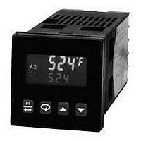
Tel +1 (717) 767-6511 Fax +1 (717) 764-0839 www.redlion.net MODELS T16 & P16 - TEMPERATURE/PROCESS CONTROLLERS GENERAL DESCRIPTION The Model T16 Controller accepts signals from a variety of temperature sensors (thermocouple or RTD), while the Model P16 Controller accepts either ...
Page 2
GENERAL SPECIFICATIONS 1. DISPLAY: 2 Line by 4-digit, LCD negative image transmissive with backlighting. Top (Process) Display: 0.3" (7.6 mm) high digits with red backlighting. Bottom (Parameter) Display: 0.2" (5.1 mm) high digits with green backlighting. 2. ANNUNCIATORS: Status Annunciators: ...
Page 3
... PART NUMBERS 18-36 VDC/24 VAC 85 to 250 VAC — T1610010 T1610000 Yes T1611110 T1611100 — T1620010 T1620000 Yes T1621110 T1621100 Yes T1641110 T1641100 — P1610010 P1610000 Yes P1611110 P1611100 — ...
Page 4
... Install them near the power entry point of the enclosure. The following EMI suppression devices (or equivalent) are recommended: Ferrite Suppression Cores for Signal and Control cables: Fair-Rite # 0443167251 (Red Lion Controls # FCOR0000) TDK # ZCAT3035-1330A Steward # 28B2029-0A0 Line Filters for input power cables: Schaffner # FN610-1/07 (Red Lion Controls # LFIL0000) Schaffner # FN670-1 ...
Page 5
S ETTING THE To insure proper operation, the Analog Output jumpers must be set to the same range selected in programming Module 2-OP. The default jumper setting is for 20 mA. The default setting in Module 2-OP is 4-20 ...
Page 6
W IRING THE WIRING CONNECTIONS All wiring connections are made to the rear screw terminals. When wiring the controller, use the numbers on the label and those embossed on the back of the case, to identify the position number ...
Page 7
R EVIEWING THE FRONT PANEL KEYS The F1 key is pressed to exit (or escape) directly to the start of the Display Loop. While in the Display Loop, the F1 key can be pressed to activate its programmed function. ...
Page 8
The values shown for the displays are the factory settings. SETPOINT VALUE (SP1 -999 9999 0 T16 0. 0 P16 SETPOINT VALUE (SP2 -999 9999 T16 2. 0 P16 Typically, the controller is operating ...
Page 9
P ROGRAMMING To enter Hidden Loop, press for 3 seconds. Note: Parameters shown bold are the only parameters visible in the Hidden Loop with Factory Settings. Setpoint and Output Power are factory set for the Display Loop. The remaining ...
Page 10
AUTO-TUNE START tUNE NO YES NO The Auto-Tune procedure of the controller sets the Proportional Band, Integral Time, Derivative Time, Digital Filter, Control Output Dampening Time, and Relative Gain (Heat/Cool) values appropriate to the characteristics of the process. This parameter ...
Page 11
MODULE INPUT TYPE tYPE SELECTION TYPE SELECTION tc tc-N tc-j tc tc-C tc LIN tc r385 tc r392 tc r672 tc rLIN ...
Page 12
F1 KEY FUNCTION F1In NONE SELECTION FUNCTION SELECTION NONE No Function A1rS Reset Alarm 1 trnF Auto/Manual Select A2rS Reset Alarm 2 SPt Setpoint Select ALrS Reset Both Alarms 7.1 MODULE INPUT TYPE tYPE ...
Page 13
INPUT VALUE SCALING POINT 2 INP2 For Key-in Method, enter the second coordinate Input Value by using the arrow keys. To ...
Page 14
MODULE CYCLE TIME CYCt to seconds 0. 0 250 The Cycle Time is entered in seconds with one tenth of a second resolution the total time for one on and one ...
Page 15
ANALOG OUTPUT RANGE (OPTIONAL) ANtP V mA 0-10 0-20 mA 4-20 4-20 Select the type of output and range. The Analog output jumpers are factory set to current. They must be changed if voltage output is desired. The Analog output ...
Page 16
MODULE AVAILABLE ALARM ACTIONS No action, the remaining Alarm None NONE parameters are not available. The alarm energizes when the Process Absolute High AbHI Value exceeds the alarm value + 1/2 (balanced hysteresis) the hysteresis value. ...
Page 17
ALARM ACTION ALARM 1 ACt1 NONE AbHI AbLO AuHI AuHI d-HI d-LO b-IN b-ot Select the action for the alarms. See Alarm Action Figures for a visual explanation. ALARM ANNUNCIATOR ALARM 1 Normal nor Reverse rEv nor With normal selection, ...
Page 18
MODULE enable Cooling in Heat/Cool applications, the Alarm 2 Action must first be set for Cooling. (For P16 Controllers, the cooling output is sometimes referred to as secondary output.) When set to cooling, the output ...
Page 19
MODULE 9 F ACTORY CALIBRATION CodE 48 The controller is fully calibrated from the factory. Recalibration is recommended every two years by qualified technicians using appropriate equipment. Calibration may be performed by using the front panel or with the ...
Page 20
Analog Output Calibration (T16 and P16) Set the controller Analog jumpers to the output type being calibrated. Connect an external meter with an accuracy of 0.05% (or better) that is capable of measuring 10. 20. terminals ...
Page 21
C M ONTROL ODE ON/OFF CONTROL The controller operates in On/Off Control when the Proportional Band is set to 0.0%. In this control mode, the process will constantly oscillate around the setpoint value. The On/Off Control Hysteresis (balanced around the ...
Page 22
TIME PROPORTIONAL PID CONTROL In Time Proportional applications, the output power is converted into output On time using the Cycle Time. For example, with a four second cycle time and 75% power, the output will be on for three seconds ...
Page 23
PID Adjustments In some applications, it may be necessary to fine tune the Auto-Tune calculated PID parameters this, a chart recorder or data logging device is needed to provide a visual means of analyzing the process. Compare the ...
Page 24
PARAMETER VALUE CHART DISPLAY LOOP DISPLAY PARAMETER FACTORY SETTING SETPOINT VALUE SP1 SP SETPOINT VALUE SP2 SP OUTPUT POWER PERCENT OP ProP * PROPORTIONAL BAND 100. 0 120 Intt * INTEGRAL TIME dErt * DERIVATIVE TIME AL-1 * ALARM 1 ...
Page 25
T16 & P16 P ROGRAMMING Q O UICK 25 VERVIEW ...
Page 26
This page intentionally left blank 26 ...
Page 27
This page intentionally left blank 27 ...
Page 28
... The Company disclaims all liability for any affirmation, promise or representation with respect to the products. The customer agrees to hold Red Lion Controls harmless from, defend, and indemnify RLC against damages, claims, and expenses arising out of subsequent sales of RLC products or products containing components manufactured by RLC and based upon personal injuries, deaths, property ...