T1620000 Red Lion Controls, T1620000 Datasheet - Page 20
T1620000
Manufacturer Part Number
T1620000
Description
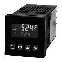
Process/Temperature Controller
Manufacturer
Red Lion Controls
Type
Temperaturer
Specifications of T1620000
Operating Temperature Max
50°C
Operating Temperature Min
0°C
Temperature Accuracy ±
0.3%
Output Voltage Max
7V
Output Voltage Min
4V
Controller Input
Thermocouple Or RTD
Brand/series
T16 Series
Dimensions
49.5mmW×49.5mmH×115.3mmD
Enclosure Rating
IP65
Input Type
RTD/Thermocouple
Ip Rating
IP65
Memory
EEPROM
Mounting Type
Panel
Output Type
Digital/SSR
Power, Rating
8 VA
Primary Type
Controller
Special Features
EEPROM
Standards
cURus, CE
Termination
Screw
Voltage, Supply
85 to 250 VAC
Thermocouple Type
J, K, T, E, R, S, B, N, C And Linear MV
Rohs Compliant
Yes
Lead Free Status / RoHS Status
Lead free / RoHS Compliant


Analog Output Calibration (T16 and P16)
Connect an external meter with an accuracy of 0.05% (or better) that is capable
of measuring 10.00 V or 20.00 mA to terminals 6 (+V/I) and 7 (-V/I). The
voltage or current calibration that is not being used must be skipped by pressing
T
Set the controller Analog jumpers to the output type being calibrated.
until End appears.
NO DISPLAY
CONTROLLER NOT WORKING
E-E2
E-CL
dddd
OPEN
SENS
OLOL
ULUL
SHrt
CONTROLLER SLUGGISH OR
NOT STABLE
ROUBLESHOOTING
[C 0v]
[CodE]
[ANCL]
PROMPT
[CAL]
[CJC]
[rtd]
C 10v
C 0c]
C 20c
For further technical assistance, contact technical support.
IN DISPLAY
IN DISPLAY
or
IN DISPLAY (T16)
IN DISPLAY (P16)
IN TOP DISPLAY
IN DISPLAY (T16)
IN TOP DISPLAY
-ddd
PROBLEM
0.00 V
10.00 V
0.00 mA
20.00 mA
EXTERNAL
METER
IN DISPLAY
Press
Press
Press
Press
Press
Press
matches listing, press
Press
matches listing, press
Press
matches listing, press
Press
matches listing, press
FRONT PANEL ACTION
.
. (T16 only)
. (T16 only)
until
for
or
or
or
or
1. Power off.
2. Brown-out condition.
3. Loose connection or improperly wired.
4. Bezel assembly not fully seated into rear of controller.
1. Incorrect setup parameters.
1. Loss of setup parameters due to noise spike or other
1. Loss of calibration parameters due to noise spike or
1. Display value exceeds 4 digit display range.
2. Defective or miscalibrated cold junction circuit.
3. Loss of setup parameters.
4. Internal malfunction.
1. Probe disconnected.
2. Broken or burned-out probe.
3. Corroded or broken terminations.
4. Excessive process temperature.
1. Input exceeds range of controller.
2. Incorrect input wiring.
3. Defective transmitter.
4. Internal malfunction.
1. Input exceeds range of controller.
2. Temperature exceeds range of input probe.
3. Defective or incorrect transmitter or probe.
4. Excessive high temperature for probe.
5. Loss of setup parameters.
1. Input is below range of controller.
2. Temperature below range of input probe.
3. Defective or incorrect transmitter or probe.
4. Excessive low temperature for probe.
5. Loss of setup parameters.
1. RTD probe shorted.
1. Incorrect PID values.
2. Incorrect probe location.
EMI event.
other EMI event.
until external meter
until external meter
until external meter
until external meter
, press
, press
.
.
.
.
.
.
CAUSE
20
rSEt and then return to CNFP. Press
overwrite all user settings with Factory Settings.
CodE 77 again. Press
return to the Display Loop. This will not overwrite any user settings but will
erase the controller calibration values. This procedure does not require any
calibration signals nor external meters. This can be used to clear calibration
error flag E-CL.
CAUTION: This procedure will result in up to ±10% reading error and the
CodE
Press and hold
CodE
Press and hold
controller will no longer be within factory specifications. For this reason, this
procedure should only be performed if meter error is outside of this range to
temporarily restore operation until the unit can be accurately calibrated.
66
77
1. Check power.
2. Verify power reading.
3. Check connections.
4. Check installation.
1. Check setup parameters.
1. Press F1 to escape, then check all setup parameters.
1. Press F1 to escape, then check controller accuracy.
1. Change resolution to display whole number and verify reading.
2. Perform cold junction calibration.
3. Check setup parameters.
4. Perform Input calibration.
1. Connect probe.
2. Replace probe.
3. Check connections.
4. Check process parameters.
1. Check input parameters.
2. Check input wiring.
3. Replace transmitter.
4. Perform input calibration.
1. Check input parameters.
2. Change to input sensor with a higher temperature range.
3. Replace transmitter or probe.
4. Reduce temperature.
5. Perform input calibration.
1. Check input parameters.
2. Change to input sensor with a lower temperature range.
3. Replace transmitter or probe.
4. Raise temperature.
5. Perform input calibration.
1. Check wiring and/or replace RTD probe.
1. See PID control.
2. Evaluate probe location.
a. Check sensor input and AC line for excessive noise.
b. If fault persists, replace controller.
a. Recalibrate controller. (See Factory Service Module code 77.)
b. Reset parameters to factory default settings.
NOMINAL CALIBRATION SETTINGS
RESTORE FACTORY SETTINGS
to display CodE 77. Press
to display CodE 66. Press
. The controller will then return to CNFP. Press
to return to the Display Loop. This will
REMEDIES
. Press and hold
. The controller will display
to display
to
Related parts for T1620000
Image
Part Number
Description
Manufacturer
Datasheet
Request
R

Part Number:
Description:
Counter
Manufacturer:
Red Lion Controls
Datasheet:
Part Number:
Description:
Miniature Length Sensor
Manufacturer:
Red Lion Controls
Datasheet:
Part Number:
Description:
Model Lsc - Single Channel Output Length Sensor
Manufacturer:
Red Lion Controls
Datasheet: