T4810000 Red Lion Controls, T4810000 Datasheet - Page 2
T4810000
Manufacturer Part Number
T4810000
Description
Process/Temperature Controller
Manufacturer
Red Lion Controls
Type
Temperaturer
Datasheet
1.T4810000.pdf
(8 pages)
Specifications of T4810000
Operating Temperature Max
50°C
Operating Temperature Min
0°C
Temperature Accuracy ±
0.3%
Output Voltage Max
250VAC
Output Voltage Min
30VDC
Controller Input
Thermocouple Or RTD
Brand/series
T48 Series
Contact Form
SPST
Current, Load
1 A @ 35 °C (Max.)
Dimensions
49.5mmW×49.5mmH×115.3mmD
Enclosure Rating
IP65
Input Type
RTD/Thermocouple
Ip Rating
IP65
Memory
EEPROM
Mounting Type
Panel
Output Type
Relay
Power, Rating
8 VA
Primary Type
Controller
Special Features
EEPROM
Standards
cURus, CE
Temperature, Ambient
0 to +50 °C (Max.)
Termination
Screw
Voltage, Rating
120⁄240 VAC
Voltage, Supply
85 to 250 VAC
Panel Cutout
1.77" × 1.77" (1⁄16 DIN)
Power Requirements
85-250 VAC
Sealing
NEMA 4X/IP65
Operating Temperature
0°C to +50°C
Thermocouple Type
J, K, T, E, R, S, B, N, Linear MV
Rohs Compliant
NA
Lead Free Status / RoHS Status
na


loops, where tighter control is required; and allows for remotely driven setpoint
signal from computers or other similar equipment. Straightforward end point
scaling with independent filtering and local/remote transfer option expand the
controller’s flexibility.
communication between a T48 and other compatible equipment such as a
printer, PLC, HMI, or a host computer. In multipoint applications (up to
thirty-two), the address number of each T48 on the line can be programmed
from 0 to 99. Data from the T48 can be interrogated or changed, and alarm
output(s) may be reset by sending the proper command code via serial
communications. PC software, SFCRM, allows for easy configuration of
controller parameters. These settings can be saved to disk for later use or used
for multi-controller down loading. On-line help is provided within the software.
front panel. The front panel meets NEMA 4X/IP65 specifications when properly
installed. Multiple units can be stacked horizontally or vertically. Modern
surface-mount technology, extensive testing, plus high immunity to noise
interference makes the controller extremely reliable in industrial environments.
SAFETY SUMMARY
manual or on equipment must be observed to ensure personal safety and to
prevent damage to either the instrument or equipment connected to it. If
equipment is used in a manner not specified by the manufacturer, the protection
provided by the equipment may be impaired.
equipped with safeguards. To do so can be potentially harmful to persons or
equipment in the event of a fault to the controller. An independent and redundant
temperature limit indicator with alarm outputs is strongly recommended.
SPECIFICATIONS
1.
2. POWER:
3. CONTROLS: Four front panel push buttons for modification and setup of
4. MEMORY: Nonvolatile E
5. MAIN SENSOR INPUT:
6. THERMOCOUPLE INPUT:
DISPLAY: Dual 4-digit
Optional Remote Setpoint input (0/4 to 20 mA) allows for cascade control
The optional RS485 serial communication interface provides two-way
The unit is constructed of a lightweight, high impact plastic case with a tinted
All safety related regulations, local codes and instructions that appear in the
Do not use the T48 to directly command motors, valves, or other actuators not
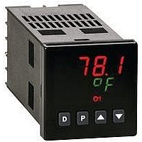
Upper Temperature Display: 0.4" (10.2 mm) high red LED
Lower Auxiliary Display: 0.3" (7.6 mm) high green LED
Display Messages:
LED Status Annunciators:
AC Versions: 85 VAC min. to 250 VAC max., 50 to 60 Hz, 8 VA max.
DC Versions:
controller functions and one external input user for parameter lockout or
other functions.
values.
Sample Period: 100 msec
Response Time: Less than 300 msec typ., 400 msec max. (to within 99% of
Failed Sensor Response:
Normal Mode Rejection: 40 dB @ 50/60 Hz (improves with increased
Common Mode Rejection: Greater than 120 dB, DC to 60 Hz
Protection: Input overload 120 VAC max. for 15 seconds max.
Types: T, E, J, K, R, S, B, N, Linear mV, software selectable
Input Impedance: 20 MΩ all types
Lead resistance effect: 0.25 µV/Ω
“OLOL”
“ULUL”
“OPEN”
“SHrt”
“...”
“-..”
%P
MN
DV
O1
A1
A2
DC Power: 18 to 36 VDC; 7 W
AC Power: 24 VAC ± 10%; 50 to 60 Hz, 9 VA
final value w/step input; typically, response is limited to response time of
probe)
Main Control Output(s): Programmable preset output
Display: “OPEN”
Alarms: Upscale drive
digital filtering.)
- Appears when measurement exceeds + sensor range.
- Appears when measurement exceeds - sensor range.
- Appears when open sensor is detected.
- Appears when shorted sensor is detected (RTD only)
- Appears when display values exceed + display range.
- Appears when display values exceed - display range.
- Lower auxiliary display shows power output in (%).
- Flashing: Controller is in manual mode.
- Lower auxiliary display shows deviation (error) from
- Main control output is active.
- Alarm #1 is active (for A1 option.).
- Alarm #2 is active OR
- Cooling output (O2) is active
temperature setpoint or shows heater current.
On: Local Setpoint (Remote Setpoint option)
Off: Remote Setpoint
2
PROM retains all programmable parameters and
2
7. RTD INPUT: 2 or 3 wire, 100 Ω platinum, alpha = 0.00385 (DIN 43760),
8. INDICATION ACCURACY: ±(0.3% of Span +1°C.) includes NIST
9. USER INPUT: Internally pulled up to +5 VDC (1 MΩ).
10. CONTROL AND ALARM OUTPUTS: (Heating, Cooling or Alarm)
11. MAIN CONTROL:
12. ALARMS: 1 or 2 alarms (optional)
Cold junction compensation: Less than ±1°C (
Resolution: 1° for all types, or 0.1° for T, E, J, K, and N only.
alpha = 0.0039162
Excitation: 150 µA typical
Resolution: 1 or 0.1 degree
Lead Resistance: 15 Ω max. per input lead
conformity, cold junction effect and A/D conversion errors at 23°C after 20
min. warm-up.
V
I
Response Time: 120 msec max.
Functions:
Relay outputs with Form A contacts:
Logic/SSR Drive Outputs:
Triac Outputs:
Control: PID or ON/OFF
Output: Time proportioning or Linear DC
Cycle time: Programmable
Auto-tune: When selected, sets proportional band, integral time, and
Probe Break Action: Programmable
Modes: Absolute high acting
OFF
IN MAX
to 50°C max. ambient temperature range. Defeated for Linear mV
indication mode.
Contact Rating: 3 A @ 250 VAC or 30 VDC (resistive load)
Life Expectancy: 100,000 cycles at max. load rating.
Rating: 45 mA @ 4 V min., 7 V nominal
Type: Isolated, Zero Crossing Detection
Rating:
Offstate Leakage Current: 7 mA max. @ 60 Hz
Operating Frequency: 20 to 400 Hz
Protection: Internal transient snubber
derivative time values.
= 1µA max.
1/10 HP @ 120 VAC (inductive load)
(Decreasing load and/or increasing cycle time, increases life
expectancy.)
Voltage: 120/240 VAC
Max. Load Current: 1 Amp @ 35°C
Min Load Current: 10 mA
TC TYPE
mV
Absolute low acting
Deviation high acting
Deviation low acting
Inside band acting
R
N
T
E
K
S
B
J
= 5.25 VDC
Program Lock
Auto/Manual Mode Select
Reset Alarms
Local/Remote Setpoint Select
+149 to +1820°C
-200 to +1250°C
+300 to +3308°F
-200 to +1300°C
-328 to +1382°F
-328 to +2282°F
-328 to +2372°F
+32 to +3214°F
-200 to +400°C
-328 to +752°F
-200 to +750°C
-200 to +760°C
-328 to 1400°F
-5.00 to +56.00
+32 to 3214°F
RTD TYPE
0 to 1768°C
0 to 1768°C
OHMS
,
RANGE
385
392
V
IL
= 0.85 V max., V
0.75 Amp @ 50°C
-328 to +1100°F
-328 to +1100°F
-200 to +600°C
-200 to +600°C
no standard
orange (+)
1.0 to 320.0
yellow (+)
violet (+)
white (+)
black (+)
black (+)
blue (+)
grey (+)
red (-)
red (-)
red (-)
red (-)
red (-)
red (-)
red (-)
red (-)
RANGE
ANSI
IH
WIRE COLOR
= 3.65 V min.,
Integral Action Lock
Setpoint Ramp Enable
Setpoint 1/Setpoint 2 Select
Serial block print
±
1.5
°
no standard
no standard
C max), error over 0
orange (+)
brown (+)
yellow (+)
brown (+)
white (+)
white (+)
white (+)
BS 1843
blue (-)
blue (-)
blue (-)
blue (-)
blue (-)
blue (-)
blue (-)
Related parts for T4810000
Image
Part Number
Description
Manufacturer
Datasheet
Request
R

Part Number:
Description:
Counter
Manufacturer:
Red Lion Controls
Datasheet:
Part Number:
Description:
Miniature Length Sensor
Manufacturer:
Red Lion Controls
Datasheet:
Part Number:
Description:
Model Lsc - Single Channel Output Length Sensor
Manufacturer:
Red Lion Controls
Datasheet: