SI-LS100MRFF BANNER ENGINEERING, SI-LS100MRFF Datasheet
SI-LS100MRFF
Specifications of SI-LS100MRFF


Related parts for SI-LS100MRFF


SI-LS100MRFF Summary of contents
Page 1
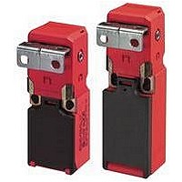
... Limit switch design (EN 50047) • Mechanically-coded actuators utilize two independent operating elements to minimize intentional tampering or defeat • Rotating head allows actuator engagement from four sides or four top positions; no tools are required to rotate head • Low-profile design for limited space requirements; only 30.5 mm (1.3") depth • ...
Page 2
... ISO 13849 (EN954-1). In addition, the user of Banner safety switches has the responsibility to ensure that all local, state, and national laws, rules, codes, and regulations relating to the use of Banner safety switches in any particular application are satisfied. Extreme care is urged that all legal requirements have been met and that all installations and maintenance instructions are followed ...
Page 3
... The mounting holes in the switch body and the actuator accept M5 screws (see dimensions, page 7). Position the switch, with its actuator fully engaged, in the mounting location and mark the mounting holes. Drill the required holes and fasten the switch body and the actuator in place ...
Page 4
... Access to the Wiring Chamber The wiring chamber is accessed via the hinged door. See Figure 1. The SI-LS83 switches have a wire entrance of M16 x 1.5. The SI-LS100 models have a wire entrance of M20 x 1.5. All models come with an adaptor to convert to 1/2"–14 NPT. M16 x 1.5 and M20 x 1 ...
Page 5
... Confirmation that the safety switch is not being used as an end stop, 4. Loosening of the switch or actuator mounting hardware, and 5. Verification that it is not possible to reach any hazard point through an opened guard (or any opening) before hazardous machine motion has completely stopped. In addition, we recommend that a qualified person check for the following on a periodic ...
Page 6
... Engagement Radius Flexible actuators (2") in all directions Actuator Extraction Force 12 Newtons (2.6 lbf) Short Circuit Protection 6 amp Slow Blow, 10 amp Fast Blow. Recommended external fusing or overload protection. Mechanical Life 1 million operations Wire Connections Stranded and solid: 20 AWG (0.5 mm Stranded: 20 AWG (0.5 mm Cable Entry SI-LS83 models: M16 x 1 ...
Page 7
... Accessories Cable Glands Used with For Cable Switch Models Diameters 3.0 to 8.0 mm SI-LS83 (0.12" to 0.31") 5.0 to 12.0 mm SI-LS100 (0.20" to 0.47") SI-LS83 and SI-LS100 Series Model SI-LS-83.. Interlock Body 30.0 mm (1.19") 38.0 mm (1.50") 2.0 mm (0.08") 83.0 mm (3.30") 5.5 mm 45.0 mm (0.22") (1.79") ...
Page 8
... WARNING . . . Spare actuators must NEVER be used to bypass or otherwise defeat the protective function of a safety switch may create an unsafe situation which could lead to serious injury or death. P/N 59622 rev. E Banner Engineering Corp., 9714 Tenth Ave. No., Minneapolis, MN USA 55441 • Phone: 763.544.3164 • www.bannerengineering.com • Email: sensors@bannerengineering.com ...