SI-LS100MRFF BANNER ENGINEERING, SI-LS100MRFF Datasheet - Page 4
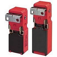
SI-LS100MRFF
Manufacturer Part Number
SI-LS100MRFF
Description
SWITCH, SAFETY INTERLOCK, 2NC/1NO, 10A
Manufacturer
BANNER ENGINEERING
Type
Interlockr
Specifications of SI-LS100MRFF
Contact Configuration
3PST-2NC / 1NO
Contact Voltage Ac Max
230V
Contact Voltage Dc Max
24V
Contact Current Ac Max
10A
Contact Current Dc Max
6A
Circuitry
3PST-2NC/1NO
Actuator Type
Flexible
Contact Form
1 NO, 2 NC
Current, Rating
10/6 AAC/ADC
Function
Safety
Ip Rating
IP65
Number Of Positions
3
Standards
UL Listed, CSA Certified, CE Marked
Temperature Rating
-30 to +80 °C
Voltage, Rating
230/24 VAC/VDC
Peak Reflow Compatible (260 C)
No
Lead Free Status / Rohs Status
RoHS Exempt Product


Machine Safety Switches –
Access to the Wiring Chamber
The wiring chamber is accessed via the hinged door. See Figure 1. The SI-LS83
switches have a wire entrance of M16 x 1.5. The SI-LS100 models have a wire entrance
of M20 x 1.5. All models come with an adaptor to convert to 1/2"–14 NPT. M16 x 1.5 and
M20 x 1.5 cable glands are available on page 7.
Connection to a Machine
As illustrated in Figure 2, a normally closed safety contact (i.e., a safety contact that is
closed when the actuator is engaged) from each of two safety switches per interlocked
guard must connect to a 2-channel safety module or safety interface in order to achieve
a control reliable interface to the master stop control elements of a machine. Examples of
appropriate safety modules include 2-channel emergency stop (E-stop) safety modules
and gate monitor safety modules.
Two functions of the safety module or safety interface are:
1. to provide a means of monitoring the contacts of both safety switches for contact
2. to provide a reset routine after closing the guard and returning the safety switch
Use only a positively driven, normally closed safety contact from each switch for
connection to the safety module. The normally open contact may be used for control
functions that are not safety-related. A typical use is to communicate switch status to a
process controller. Refer to the installation instructions provided with the safety modules
for more information regarding the interface of the safety module to the machine stop
control elements.
Figure 2. Connect two redundant safety switches per interlock guard to an appropriate
failure, and to prevent the machine from restarting if either switch fails; and
contacts to their closed position. This prevents the controlled machinery from restarting
by simply reinserting the safety switch actuators. This necessary reset function is
required by ANSI B11 and NFPA 79 machine safety standards.
P/N 59622 rev. E
2-channel Gate Monitor Module, etc.)
Channel
Switch
Safety
2-channel input safety module.
Input
#1
#1
(2-channel E-stop Module
2-channel Safety Module
Channel
Switch
Safety
Input
#2
#2
Electrical Installation
NOTE: Refer to the installation instructions provided with the
Single gate
or
guard
safety module for information regarding the interface of
the safety module to the machine stop control elements.
SI-LS83 and SI-LS100 Series
Banner Engineering Corp. • Minneapolis, MN U.S.A.
www.bannerengineering.com • Tel: 763.544.3164
hazard point through an opened guard
(or any opening) before hazardous
machine motion has completely stopped.
Please reference OSHA CFR 1910.217
and ANSI B11 standards (see page 2) for
information on determining safety distances
and safe opening sizes for your guarding
devices.
must be used for each interlock guard
to achieve control reliability or Safety
Category (per ISO 1389-1, EN 95-1) of
a machine stop circuit. Use of only one
safety switch per interlock guard is not
recommended.
In addition, normally closed safety contacts
from each of the two safety switches should
be connected to the two separate inputs of a
2-channel safety module or safety interface,
as illustrated in Figure 2. This is required to
provide monitoring for safety switch contact
failure, and to provide the necessary reset
routine, as required by IEC 60204-1 and
NFPA 79 machine safety standards.
Monitoring multiple guards with a series
connection of multiple safety interlock
switches is not a Safety Category
Application (per ISO 1389-1, EN 95-1).
A single failure may be masked or
not detected at all. When such a
configuration is used, procedures must
be performed regularly to verify proper
operation of each switch.
WARNING . . .
It must not be possible for
personnel to reach any
WARNING . . .
Connection of Safety
Interlock Switches
CAUTION . . .
Electrical Installation
Two safety switches
Series
Related parts for SI-LS100MRFF
Image
Part Number
Description
Manufacturer
Datasheet
Request
R

Part Number:
Description:
Photoelectric Sensor
Manufacturer:
BANNER ENGINEERING
Datasheet:

Part Number:
Description:
Photoelectric Sensor
Manufacturer:
BANNER ENGINEERING
Datasheet:

Part Number:
Description:
LEDIR70XD4-XM-81039 MAX INTENS STROBE ONLY NO BANNER MARKS
Manufacturer:
BANNER ENGINEERING
Part Number:
Description:
M18SP6DL-72225 LABELED MOELLER NO BANNER MARKINGS BULK PACK
Manufacturer:
BANNER ENGINEERING
Part Number:
Description:
M18SP6DLQ-72226 LABLED MOELLER NO BANNER MARKINGS BULK PACK
Manufacturer:
BANNER ENGINEERING
Part Number:
Description:
M18SP6L-72223 LABELED MOELLER NO BANNER MARKINGS BULK PACK
Manufacturer:
BANNER ENGINEERING
Part Number:
Description:
M18SP6LQ-72224 LABELED MOELLER NO BANNER MARKINGS BULK PACK
Manufacturer:
BANNER ENGINEERING
Part Number:
Description:
P4D1-77908 P4 DRIVER GENERIC NO BANNER MARKINGS RESALE TO CUSTOMER
Manufacturer:
BANNER ENGINEERING
Part Number:
Description:
Photoelectric Sensor
Manufacturer:
BANNER ENGINEERING
Datasheet:

Part Number:
Description:
Programmable Indicator Light
Manufacturer:
BANNER ENGINEERING
Datasheet:
Part Number:
Description:
INDICATOR LED PANEL 50MM GRN/RED/YEL 30V
Manufacturer:
BANNER ENGINEERING
Datasheet:
Part Number:
Description:
Programmable Indicator Light
Manufacturer:
BANNER ENGINEERING
Datasheet: