VZA42P2BAA Omron, VZA42P2BAA Datasheet - Page 10
VZA42P2BAA
Manufacturer Part Number
VZA42P2BAA
Description
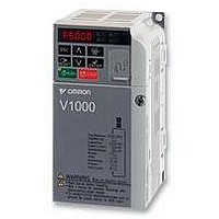
INVERTER DRIVE, 2.2KW, 400VAC, 5.5A
Manufacturer
Omron
Datasheet
1.VZA42P2BAA.pdf
(18 pages)
Specifications of VZA42P2BAA
Supply Voltage Range
380VAC To 480VAC
No. Of Phases
Three
Power Rating
2.2kW
Output Voltage Max
480V
Frequency Range
57Hz To 63Hz
Svhc
No SVHC (15-Dec-2010)
Approval Bodies
CE, CUL, TUV, UL
External Depth
154mm
Rohs Compliant
Yes
Lead Free Status / RoHS Status
Lead free / RoHS Compliant


Main circuit
Control Circuit
10
Analog
signals
output
Type
Stop
Cmd
Fast
U/T1, V/T2, W/T3
R/L1, S/L2, T/L3
Terminal
B1, B2
+2, +1
+1, –
FR1
FR2
No.
MA
MB
MC
PM
AM
SC
RP
FC
HC
PC
AC
S1
S2
S3
S4
S5
S6
FS
H1
H2
P1
P2
R+
R–
S+
S–
Main circuit power supply input
Inverter output
Braking resistor connection
DC reactor connection
DC power supply input
Grounding
Signal name
Multi-function input selection 1
Multi-function input selection 2
Multi-function input selection 3
Multi-function input selection 4
Multi-function input selection 5
Multi-function input selection 6
Multi-function input selection
Common
Main Speed Cmd Pulse Train Input 32 kHz max.
Power Supply for Frequency Setting +10 V (allowable max current 20 mA)
Main Speed Freq Ref
Frequency reference common
Power Supply Fast Stop Cmd
Special Digital input
Special Digital input
NO contact output
NC Output
Relay Output common
Photocoupler output 1
Photocoupler output 2
Photocoupler output common
Pulse train Output
Analog monitor output
Analog monitor common
Communication input (+)
Communication input (–)
Communication output (+)
Communication output (–)
Name
Used to connect line power to the drive.
Drives with single-phase 200 V input power use only terminals R/L1 and S/L2
(T/L3 is not connected to anything)
Used to connect the motor
Available for connecting a braking resistor or the braking resistor unit option.
Remove the short bar between +2 and +1 when connecting DC reactor (option)
For power supply input (+1: positive electrode; – : negative electrode)*
For grounding (grounding should conform to the local grounding code.)
Function
Factory setting: runs when CLOSED, stops when OPEN.
Factory setting: runs when CLOSED, stops when OPEN.
Factory setting: External Fault (N.O.)
Factory setting: Fault reset
Factory setting: Multi-step speed cmd 1
Factory setting: Multi-step speed cmd 2
Common for control signal
Voltage input or current input
0 to +10 VDC (20 kΩ) (resolution 1/1000)
4 to 20 mA (250 Ω) or 0 to 20 mA (250 Ω) Resolution: 1/500
0 V
+24 V (max allowable current 10 mA)
Open: Fast Stop
Factory setting: "fault"
Factory setting: During run
Factory setting: Frequency Agree
0 V
max 33 kHz
Factory setting: "output frequency" 0 to +10 V output Resolution: 1/1000
0 V
For MEMOBUS communication
operation by RS-485 or RS-422 communication is available.
Closed: Normal Operation
Function (signal level)
Frequency inverters
Signal level
24 VDC, 8 mA
photocoupler
insulation
Contact capacity
250 VAC,
1 A or less
30 VDC, 1 A
or less
Photocoupler output:
+48 VDC, 50 mA or
less
0 to 10 V 2 mA
or less
Resolution: 8 bits
RS-485/422
MEMOBUS
protocol
Related parts for VZA42P2BAA
Image
Part Number
Description
Manufacturer
Datasheet
Request
R

Part Number:
Description:
G6S-2GLow Signal Relay
Manufacturer:
Omron Corporation
Datasheet:
Part Number:
Description:
Compact, Low-cost, SSR Switching 5 to 20 A
Manufacturer:
Omron Corporation
Datasheet:
Part Number:
Description:
Manufacturer:
Omron Corporation
Datasheet:
Part Number:
Description:
Manufacturer:
Omron Corporation
Datasheet:
Part Number:
Description:
Manufacturer:
Omron Corporation
Datasheet:
Part Number:
Description:
Manufacturer:
Omron Corporation
Datasheet:
Part Number:
Description:
Manufacturer:
Omron Corporation
Datasheet:
Part Number:
Description:
Manufacturer:
Omron Corporation
Datasheet: