LPAX0500 Red Lion Controls, LPAX0500 Datasheet - Page 3
LPAX0500
Manufacturer Part Number
LPAX0500
Description
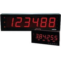
Multifunction Meter
Manufacturer
Red Lion Controls
Type
Multi-Functionr
Datasheet
1.LPAX0500.pdf
(4 pages)
Specifications of LPAX0500
No. Of Digits / Alpha
5
Panel Cutout Height
3.63"
Panel Cutout Width
9.29"
Signal Input Type
Current, Process, Strain Gage, Thermocouple, Voltage
Connection Type
Cage-Clamp
Cut Out, Panel
9.29×3.63 "
Digit Height
4
Dimensions
10"L×4.77"W×4.75"H
Display Digit Height
1.5 "
Display Type
LED
Function
Ammeter/Process/Resistance/Strain Gage/Temperature/Voltage
Material, Casing
Steel
Number Of Digits
6
Primary Type
Electronic
Range, Measurement
-19999 to 99999
Termination
Cage Clamp
Voltage, Input
85 to 250 VAC
Voltage, Supply
85 to 250 VAC/11 to 36 VDC or 24 VAC
Sealing
NEMA 4/IP65
Character Size
1.5"
Color
Red
Rohs Compliant
Yes
Lead Free Status / RoHS Status
Lead free / RoHS Compliant
For Use With
Red Lion MPAXD000, MPAXH000, MPAXP000 And MPAXT000 MPAX Modules


and any option cards be assembled first. This will allow you the
opportunity to insure all the boards are fitted properly into their
connectors.
Installing the Option Cards
cards, they should be installed into the
MPAX before it is installed into the
LPAX Display. Refer to the
literature enclosed with the option
cards for installation instruction.
Installing the MPAX
align the module with the opening
in the LPAX case, as illustrated.
The module must be oriented as
shown, with terminal #1 toward the
top of the LPAX case. Carefully
slide the module into the LPAX case.
The LPAX and MPAX connectors will begin
to engage about
apply a small amount of pressure to the rear of the
MPAX module to fully engage the connection. Be sure the
module fully snaps into the slots at the rear of the LPAX case. The
display is ready for installation.
Removing The MPAX Module
remove all power and load circuits. Then insert a flat
screwdriver blade (
between the LPAX rear cover plate and the
module’s plastic cover as illustrated in Figure
2. Twist the screwdriver in the direction
shown to disengage the internal
connectors
squeezing and pulling back
on the rear finger tabs
(top
Carefully slide the
module out of the
LPAX case, keeping it
properly aligned with
the case opening.
1.0 ASSEMBLING THE DISPLAY
Prior to installing the LPAX Display, it is recommended that the MPAX
If your application requires option
To install the MPAX Module,
To remove the MPAX Module from the LPAX Display, first
and
CAUTION: The MPAX main circuit board and the option cards
bottom).
contain static sensitive components. Before handling the module
or the cards, discharge static charges from your body by
touching a grounded bare metal object. Handle the module by
the rear plastic cover only, and the option cards by the board
edges. Dirt, oil or other contaminants that contact the circuit
boards or components can adversely affect circuit operation.
while
¼"
from the bottom. At this point,
3
/
16
" or
firmly
1
/
4
") into the narrow slot
Figure 1, Installing an MPAX Module and Option Cards
Figure 2, Removing an MPAX Module
3
Installing the Labels
labels must be applied to the rear of the LPAX in the positions shown in the
drawing.
Each option card and the MPAX are shipped with a connection label. These
NOTE: All module and option card labels must be installed as
WARNING: Exposed line voltage exists on the MPAX main circuit
shown for safety purposes.
board and the option cards. DO NOT apply power to the
module OR load circuits until the module is properly installed
in the LPAX case.
Related parts for LPAX0500
Image
Part Number
Description
Manufacturer
Datasheet
Request
R

Part Number:
Description:
Counter
Manufacturer:
Red Lion Controls
Datasheet:
Part Number:
Description:
Miniature Length Sensor
Manufacturer:
Red Lion Controls
Datasheet:
Part Number:
Description:
Model Lsc - Single Channel Output Length Sensor
Manufacturer:
Red Lion Controls
Datasheet: