H3CR-F8 24AC/DC Omron, H3CR-F8 24AC/DC Datasheet - Page 11
H3CR-F8 24AC/DC
Manufacturer Part Number
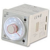
H3CR-F8 24AC/DC
Description
Electronic Multifunction Timer
Manufacturer
Omron
Datasheet
1.H3CR-F8_100-240AC.pdf
(55 pages)
Specifications of H3CR-F8 24AC/DC
Time Range
0.05 Sec To 30 Hr
Height
48mm
External Width
48mm
External Depth
78mm


H3CR-A
Gate Signal Input
D:
Signal
OFF-delay
E:
Interval
G:
Signal
ON/OFF-
delay
J:
One-shot
output
Operating
Output
relay
Power
Reset
Start
Gate
Note: 1. This timing chart indicates the gate input in op-
mode
ON
OFF
ON
OFF
ON
OFF
ON
OFF
ON
OFF
2. The set time is the sum of t
3. H3CR-AP model incorporates start input only.
Output relay (NC)
Output relay (NO)
(Output indicator)
erating mode A (ON-delay operation).
Output relay (NC)
Output relay (NO)
(Output indicator)
Output relay (NO)
(Output indicator)
Output relay (NC)
Power indicator
Output relay (NO)
(Output indicator)
Power indicator
Output relay (NC)
Power indicator
Power indicator
t
1
Power
Reset
Power
Reset
Start
Power
Reset
Start
Reset
Power
Start
Start
t
2
1 0.6 s
(Fixed)
1
and t
2
.
1 0.6 s
Timing chart
(Fixed)
(see note)
Output
Basic operation
Power
Note: Start input is valid and re-trigger-
Start
(see note)
Output
Basic operation
Power
Note: Start input is valid and re-
Start
able while the Timer is in operation.
(see note)
t
Basic operation
Note: Start input is valid and
Output
Power
Start
triggerable while the Timer
is in operation.
Note: Start input is valid and
t
(see note)
Basic operation
Power
Output
t
re-triggerable
the Timer is in opera-
tion.
Start
t
re-triggerable while the
Timer is in operation.
t
1 0.6 s
(Fixed)
t
H3CR-A
t
while
13
Related parts for H3CR-F8 24AC/DC
Image
Part Number
Description
Manufacturer
Datasheet
Request
R

Part Number:
Description:
RELAY REPEAT CYCLE ANALOG 30HRS
Manufacturer:
Omron
Datasheet:

Part Number:
Description:
TIMER REPEAT CYCLE
Manufacturer:
Omron
Datasheet:

Part Number:
Description:
RELAY REPEAT CYCLE ANALOG 300HRS
Manufacturer:
Omron
Datasheet:
Part Number:
Description:
RELAY REPEAT CYCLE ANALOG 30HRS
Manufacturer:
Omron
Datasheet:

Part Number:
Description:
SOLID STATE TIMER, DPDT, 30H, 240VAC
Manufacturer:
Omron
Datasheet:

Part Number:
Description:
Timer; Repeat Cycle; 1.2s-300h; E-Mech; Ctrl-V 100-240AC; 5A@250VAC/30VDC; 8-Pin Octal
Manufacturer:
Omron Automation
Datasheet:

Part Number:
Description:
TIMER, RECYCLING
Manufacturer:
Omron
Datasheet:

Part Number:
Description:
RELAY REPEAT CYCLE ANLG 30HRS
Manufacturer:
Omron
Datasheet:
Part Number:
Description:
TIMER REPEAT CYCLE
Manufacturer:
Omron
Datasheet:

Part Number:
Description:
Timer Repeat Cycle
Manufacturer:
Omron
Datasheet:
Part Number:
Description:
G6S-2GLow Signal Relay
Manufacturer:
Omron Corporation
Datasheet:
Part Number:
Description:
Compact, Low-cost, SSR Switching 5 to 20 A
Manufacturer:
Omron Corporation
Datasheet:
Part Number:
Description:
Manufacturer:
Omron Corporation
Datasheet: