H3CR-F8 24AC/DC Omron, H3CR-F8 24AC/DC Datasheet - Page 23
H3CR-F8 24AC/DC
Manufacturer Part Number
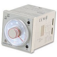
H3CR-F8 24AC/DC
Description
Electronic Multifunction Timer
Manufacturer
Omron
Datasheet
1.H3CR-F8_100-240AC.pdf
(55 pages)
Specifications of H3CR-F8 24AC/DC
Time Range
0.05 Sec To 30 Hr
Height
48mm
External Width
48mm
External Depth
78mm


H3CR-F
Note: A power supply with a ripple of 20% max. (single-phase power supply with full-wave rectification) can be used with each DC Model.
Rated supply voltage (see note)
Operating voltage range
Power reset
Power consumption
Control outputs
Accuracy of operating
time
Setting error
Reset time
Reset voltage
Influence of voltage
Influence of
temperature
Insulation resistance
Dielectric strength
Impulse withstand
voltage
Noise immunity
Static immunity
Vibration resistance
Shock resistance
Ambient temperature
Ambient humidity
Life expectancy
EMC
Case color
Enclosure ratings
Weight
Ratings
Characteristics
0.1 s max.
10 % max. of rated voltage
100 M min. (at 500 VDC)
2,000 VAC, 50/60 Hz for 1 min (between current-carrying metal parts and exposed non-current-carrying
metal parts)
2,000 VAC, 50/60 Hz for 1 min (between control output terminals and operating circuit)
2,000 VAC, 50/60 Hz for 1 min (between contacts of different polarities)
1,000 VAC, 50/60 Hz for 1 min (between contacts not located next to each other)
3 kV (between power terminals) for 100 to 240 VAC, 48 to 125 VDC
1 kV for 12 VDC, 24 VAC/DC
4.5 kV (between current-carrying terminal and exposed non-current-carrying metal parts) for 100 to 240 VAC,
48 to 125 VDC
1.5 kV for 12 VDC, 24 VAC/DC
rise)
Malfunction: 8 kV
Destruction: 15 kV
Destruction:10 to 55 Hz with 0.75-mm single amplitude for 2 hrs each in three directions
Malfunction:10 to 55 Hz with 0.5-mm single amplitude for 10 min each in three directions
Destruction: 980 m/s
Malfunction: 98 m/s
Operating:–10 C to 55 C (with no icing)
Storage: –25 C to 65 C (with no icing)
Operating: 35% to 85%
Mechanical:20 million operations min. (under no load at 1,800 operations/h)
Electrical:
(EMI)
Emission Enclosure:
Emission AC Mains:
(EMS)
Immunity ESD:
Immunity RF-interference from AM Radio Waves:
Immunity RF-interference from Pulse-modulated Radio Waves:
Immunity Conducted Disturbance: ENV50141:
Immunity Burst:
Immunity Surge:
Light Gray (Munsell 5Y7/1)
IP40 (panel surface)
Approx. 100 g
0.2% FS max. ( 0.2% FS 10 ms max. in ranges of 1.2 and 3 s)
5% FS 50 ms max.
0.2% FS max. ( 0.2% FS 10 ms max. in ranges of 1.2 and 3 s)
1% FS max. ( 1% FS 10 ms max. in ranges of 1.2 and 3s)
1.5 kV (between power terminals), square-wave noise by noise simulator (pulse width: 100 ns/1 s, 1-ns
400 V for 12 VDC
100,000 operations min. (5 A at 250 VAC, resistive load at 1,800 operations/h)
100 to 240 VAC (50/60 Hz),12 VDC, 24 VAC/DC (50/60 Hz), 48 to 125 VDC
85% to 110% of rated supply voltage; 90% to 110% with 12-VDC models
Minimum power-opening time: 0.1 s
100 to 240 VAC: approx. 10 VA (2.1 W) at 240 VAC
24 VAC/VDC:
48 to 125 VDC:
12 VDC:
Contact output: 5 A at 250 VAC/30 VDC, resistive load (cos = 1)
2
2
three times each in six directions
three times each in six directions
approx. 2 VA (1.7 W) at 24 VAC
approx. 1 W at 24 VDC
approx. 1.5 W at 125 VDC
approx. 1 W at 12 VDC
EN50081-2
EN55011 Group 1 class A
EN55011 Group 1 class A
EN50082-2
EN61000-4-2:
EN61000-4-4:
EN61000-4-5:
4 kV contact discharge (level 2)
8 kV air discharge (level 3)
ENV50140: 10 V/m (80 MHz to 1 GHz)
ENV50204: 10 V/m (900 5 MHz) (level 3)
10 V (0.15 to 80 MHz) (level 3)
2 kV power-line (level 3)
2 kV I/O signal-line (level 4)
1 kV line to line (level 3)
2 kV line to ground (level 3)
(level 3)
H3CR-F
25
Related parts for H3CR-F8 24AC/DC
Image
Part Number
Description
Manufacturer
Datasheet
Request
R

Part Number:
Description:
RELAY REPEAT CYCLE ANALOG 30HRS
Manufacturer:
Omron
Datasheet:

Part Number:
Description:
TIMER REPEAT CYCLE
Manufacturer:
Omron
Datasheet:

Part Number:
Description:
RELAY REPEAT CYCLE ANALOG 300HRS
Manufacturer:
Omron
Datasheet:
Part Number:
Description:
RELAY REPEAT CYCLE ANALOG 30HRS
Manufacturer:
Omron
Datasheet:

Part Number:
Description:
SOLID STATE TIMER, DPDT, 30H, 240VAC
Manufacturer:
Omron
Datasheet:

Part Number:
Description:
Timer; Repeat Cycle; 1.2s-300h; E-Mech; Ctrl-V 100-240AC; 5A@250VAC/30VDC; 8-Pin Octal
Manufacturer:
Omron Automation
Datasheet:

Part Number:
Description:
TIMER, RECYCLING
Manufacturer:
Omron
Datasheet:

Part Number:
Description:
RELAY REPEAT CYCLE ANLG 30HRS
Manufacturer:
Omron
Datasheet:
Part Number:
Description:
TIMER REPEAT CYCLE
Manufacturer:
Omron
Datasheet:

Part Number:
Description:
Timer Repeat Cycle
Manufacturer:
Omron
Datasheet:
Part Number:
Description:
G6S-2GLow Signal Relay
Manufacturer:
Omron Corporation
Datasheet:
Part Number:
Description:
Compact, Low-cost, SSR Switching 5 to 20 A
Manufacturer:
Omron Corporation
Datasheet:
Part Number:
Description:
Manufacturer:
Omron Corporation
Datasheet: