K3HBPPB 100/240VAC Omron, K3HBPPB 100/240VAC Datasheet - Page 13
K3HBPPB 100/240VAC
Manufacturer Part Number
K3HBPPB 100/240VAC
Description
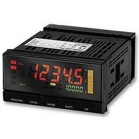
METER, PERIOD, V/NV/PNP, 100/240AC
Manufacturer
Omron
Datasheet
1.K3HBRNB_100240VAC.pdf
(32 pages)
Specifications of K3HBPPB 100/240VAC
No. Of Digits / Alpha
5
Power Consumption
18VA
Svhc
No SVHC (15-Dec-2010)
External Depth
95mm
External Length / Height
48mm
Operating Temperature Max
55°C
Operating Temperature Min
-10°C
Approval Bodies
CE, CRUus
Display
Backlit LCD Display
Rohs Compliant
Yes
Lead Free Status / RoHS Status
Lead free / RoHS Compliant


Operation
■ Functions (Operating Modes)
F1 to F6
These functions use the internal system clock to measure the time between pulses or the pulse ON time and then display time measurements or
a variety of other calculations.
Passing speed
Cycle
Time difference
Time band
Measuring length
Interval
F1
Passing
speed
F2
Cycle
F3
Time dif-
ference
Function
Function name
The reciprocal of the time (T) from input A ON to input
B ON is multiplied by 60 and displayed.
• Recovery time (T
æ
ç
ç
è
Measures and displays input A cycle (T).
æ
ç
ç
è
Displays the time (T) from input A ON to input B ON.
• Recovery time (TR) of 20 ms is required before
æ
ç
ç
è
HOLD input
Input A
Input B
HOLD input
Display
Input A
Input B
HOLD input
Display
Display
starting the next measurement.
Input A
starting the next measurement.
Display unit:
Display unit:
Display unit:
mm/s, m/s
m/min, km/h, etc.
ms, s, min.,
min.s.1/10 s
ms, s, min.,
min.s.1/10 s
Measurement range: 20 ms to 3,200 s
Measurement range: 10 ms to 3,200 s
T
f1
f2
f3
f4
f5
f6
1
T
1
Function No.
T
T
R
1
1
T
T
1
R
ö
÷
÷
ø
ö
÷
÷
ø
T
60
T
R
2
2
T
) of 20 ms is required before
1
T
Operation
2
ö
÷
÷
ø
T
T
T
3
R
1
T
R
T
T
4
3
1
T
T
T
2
3
2
Example: F1 Passing Speed
system clock
60
T
Internal
R
Input A
Input B
T
T
R
5
T
T
4
3
T
4
1
1
T
T
4
5
60
T
4
T
Measuring workpiece passing speed between A and B
Measuring feed cycles for parts
Measuring workpiece passing time
between A and B
B
B
1
A
A
Timer Interval Indicator
The time (T) between input A pulse and input B pulse
is measured by the internal system clock. If, for
example, the system clock measures 100,000 counts
during time T, then
Operation image (application)
T = 1 system clock count (0.5 s)
T = 0.05 s
F1 (the passing speed) is calculated internally
using the formula
display, in this example, would be
1200 (m/min).
Measuring the length of a
workpiece step by changing
prescale values.
1
T
K3HB-P
60 (m/min), and the
0.05 s
100,000
1
60=
13
Related parts for K3HBPPB 100/240VAC
Image
Part Number
Description
Manufacturer
Datasheet
Request
R

Part Number:
Description:
G6S-2GLow Signal Relay
Manufacturer:
Omron Corporation
Datasheet:
Part Number:
Description:
Compact, Low-cost, SSR Switching 5 to 20 A
Manufacturer:
Omron Corporation
Datasheet:
Part Number:
Description:
Manufacturer:
Omron Corporation
Datasheet:
Part Number:
Description:
Manufacturer:
Omron Corporation
Datasheet:
Part Number:
Description:
Manufacturer:
Omron Corporation
Datasheet:
Part Number:
Description:
Manufacturer:
Omron Corporation
Datasheet:
Part Number:
Description:
Manufacturer:
Omron Corporation
Datasheet:
Part Number:
Description:
Manufacturer:
Omron Corporation
Datasheet: